Download
1 / 29
290 likes | 412 Views
This chapter delves into the Entity-Relationship (E-R) Model, a vital framework for database design. It highlights how the E-R model captures the logical properties of a mini-world, aiding in conceptual-level modeling that is not restricted to any specific database management system (DBMS). Key elements such as entities, attributes, and relationships are discussed, along with their representations in E-R diagrams. It also explains the significance of keys, including primary, candidate, and foreign keys, and the various types and cardinalities of relationships, all essential for establishing data integrity and structure.

E N D
Chapter 3The Entity Relationship Model Spring 2014
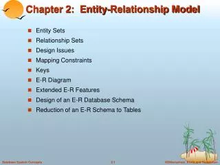
Purpose of E-R Model • Facilitates database design • Express logical properties of mini-world of interest within enterprise - Universe of Discourse • Conceptual level model • Not limited to any particular DBMS • E-R diagrams used as design tools • A semantic model – captures meanings
Symbols used in E-R Diagram • Entity – rectangle • Attribute – oval • Relationship – diamond • Link - line
Entity • Object that exists and that can be distinguished from other objects • Can be person, place, event, object, concept in the real world • Can be physical object or abstraction • Entity instance is a particular person, place, etc. • Entity type is a category of entities • Entity set is a collection of entities of same type-must be well-defined • Entity type forms intension of entity – permanent definition part • Entity instances form extension of entity – all instances that fulfill the definition at the moment • In E-R diagram, rectangle represents entity set
Attributes • Defining properties or qualities of entity type • Represented by oval on E-R diagram • Domain – set of allowable values for attribute • Credit hours might be integer values between 0 and 150 • lastName might be all legal last names – a string that might also include apostrophes, blanks, hyphens, or other special characters • Attribute maps entity set to domain • May have null values for some entity instances – no mapping to domain for those instances
Attributes (cont.) Students email • May be multi-valued – use double oval on E-R diagram (e.g., student may have more than one email address) • May be composite – use oval for composite attribute, with ovals for components connected to it by lines • May be derived – use dashed oval address zip state street city age Faculty
Keys • Superkey: attribute or set of attributes that uniquely identifies an entity (can always tell one entity instance from another) • stuId is superkey for Student entity • stuId, credits together form a superkey, because stuId is a superkey • Composite key: key with more than one attribute • courseNumber, sectionNumber, semester make up a composite key • Candidate key: superkey such that no proper subset of its attributes is also a superkey (minimal superkey –no unnecessary attributes) • Although stuId, credits is a superkey, only stuId is a candidate key • courseNumber, sectionNumber, semester is a candidate (no one attribute is a superkey) • If Student entity contains stuId and ssan as atributes, both stuId and ssan are candidate keys
Keys (cont.) • Primary key: the candidate key actually used for identifying entities and accessing records • Alternate key: candidate key not used for primary key • Secondary key: attribute or set of attributes used for accessing records, but not necessarily unique • lastName might be used to find instances in Student, to help narrow down the results • Foreign key: term used in relational model (but not in the E-R model) for an attribute that is primary key of a table and is used to establish a relationship, usually with another table, where it appears as an attribute also • stuId in Enroll entity
Relationships • Connections or interactions between entity instances • Represented by diamond on E-R diagram • Relationship type – category of relationships • Relationship set – collection of relationships of same type, consists of relationship instances – relationships that exist at a given moment • Type forms intension; set forms extension of relationship • Relationship can have descriptive attributes • Degree of relationship • Binary – links two entity sets; set of ordered pairs • Ternary – links three entity sets; ordered triples • N-ary – links n entity sets; ordered n-tuples • Note: ternary relationships may sometimes be replaced by two binary relationships (see Figure 3.6 and Figure 3.13)
Replace Ternary Relationship with Two Binary Relationships Binary Relationship Ternary Relationship
Cardinality of Relationships • Number of entity instances to which another entity can map under the relationship • One-to-one: X:Y is 1:1 is each entity in X is associated with at most one entity in Y and each entity in Y with at most one entity in X. • One-to-many: X:Y is 1:M is each entity in X can be associated with many entities in Y, but each entity in Y with at most one entity in X. • Many-to-many: X:Y is M:M if each entity in X can be associated with many entities in Y, and each entity in Y with many entities in X (many=more than one) Figure 3.7shows several representation methods
Showing Cardinalities on ER DiagramOne: 1Many: M, n 1 M Faculty Class Faculty- Class Chair- Dept Chairperson Department 1 1 Enroll Student Class N M
Showing Cardinalities on ER DiagramOne: Single ArrowMany: Double Arrow Faculty- Class Faculty Class Chair- Dept Chairperson Department Enroll Student Class
Showing Cardinalities on ER DiagramOne: Single ArrowMany: No Arrow Faculty- Class Faculty Class Chair- Dept Chairperson Department Enroll Student Class
Showing Cardinalities on ER DiagramOne: No ArrowMany: Big Dot Faculty- Class Faculty Class Chair- Dept Chairperson Department Enroll Student Class
Showing Cardinalities on ER DiagramOne: No ArrowMany: Crow’s Feet Faculty- Class Faculty Class Chair- Dept Chairperson Department Enroll Student Class
Relationship Participation Constraints • Total participation • Every member of entity set must participate in the relationship • Represented by double line from entity rectangle to relationship diamond • Partial participation • Not every entity instance must participate • Represented by single line from entity rectangle to relationship diamond
Relationship Participation Constraints • Partial participation • Not every entity instance must participate • Represented by single line from entity rectangle to relationship diamond • Some students may not be enrolled in any classes, some classes may not have any students • Total participation • Every member of entity set must participate in the relationship • Represented by double line from entity rectangle to relationship diamond • Some students may not be enrolled in any classes, some classes may not have any students • Some faculty may not teach any classes, but every class must have a faculty member teaching it Student Faculty Teaches Enroll Class
Roles • Role: function that an entity plays in a relationship • Optional to name role of each entity, but helpful in cases of • Recursive relationship – entity set relates to itself • Multiple relationships between same entity sets
Roles: Examples 1 Chairperson Chair- Member Faculty M Members Teaches M teaches M is taught by Faculty Student M is advised by 1 Advises Advise
Existence Dependency and Weak Entities • Entity Y is existence dependent on entity X is each instance of Y must have a corresponding instance of X • Y must have total participation in its relationship with X • If Y does not have its own candidate key, Y is called a weak entity, and X is strong entity • Weak entity may have a partial key, a discriminator, that distinguishes instances of the weak entity that are related to the same strong entity • Use double rectangle for weak entity, with double diamond for relationship connecting it to its strong entity • Note: not all existence dependent entities are weak – the lack of a key is essential to definition
Existence Dependency and Weak EntitiesExample facId Faculty name rank IsRated date Evaluation rater rating
deptCode office ER Diagram Example deptName Department Employs Chairs HasMajor isbn title Offers Textbook publisher stuId facId author lastName Faculty lastName Student firstName credit Faculty- Class- Textbook major firstName rank Teaches
E-R Diagram description • Student: stuId, lastName, firstName, major, credits • Each student has a unique id and has at most one major • Department: deptCode, deptName, office • Each department has a unique code and a unique name, and that each department has one office designated as the departmental office • Faculty: facId, lastName, firstName, rank • facId is unique and that every faculty member must belong to department. One faculty member in each department is the chairperson. • Class: classNumber, sched, room • classNumber consists of deptCode, courseNumber, section • Textbook: isbn, author, title, publisher • A book can have multiple authors • Evaluation: date, rater, rating • Evaluation is a weak entity, dependent on Faculty