Download

1 / 44
440 likes | 460 Views
Latest updates on LHeC design, constraints, and R&D technologies. Dialogue on concerning the two chief world systems.

E N D
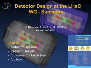
Detector Design at the LHeC WG - Summary P. Kostka, A. Polini, R. Wallny for the LHeC WGs • Outline • Detector Session • Present Design • Outcome of Discussion • Outlook
Latest updates on LHeC design, constrains, R&D Technologies Very interesting discussions Dialogue on Concerning the Two Chief World Systems Detector Sessions H. Van Der Graaf
Aim of present studies • Prove together with Physics & Machine WG the feasibility and the physics potential • Establish the Machine and the Interaction Region constrains (beam-pipe, synchr. rad, magnets) • Provide a detector baseline within reach of currently available and established technologies • Verify that such solution already fulfills the physics requirements • Foresee more advanced options means R&D available by the time of detector construction LHeC Workshop, Chavannes de Bogis, 12th 13h October 2010 2 Kostka, Polini, Wallny
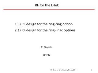
1 Ring-Ring Option B. Holzer B. Holzer • Hi Lumi / Low Lumi ~ 1.8 • Moving towards 1 option only?
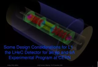
Linac-Ring Option 2/3 9 m 0.4 T bending dipoles inside the main detector 5
Requirements for the LHC experimental vacuum systems Choice of beampipe materials and sections Preliminary calculations of LHeC geometries Conical beampipes Summary Preliminary View on the LHeC Experimental Vacuum Chambers Jonathan Bosch - University of Manchester And Ray Veness - TE/VSC 11/13/10
LHC requirements The combined requirements of LHC machine and experiments (of which not all have been considered here) place a serious limit on the choice of materials and forms for beampipes. Preliminary analysis Preliminary calculations have been made for simple ‘solid’, elliptical geometries made from aluminium, titanium and beryllium. In beryllium, thickness in the order of 1 mm (for 72x58mm) and 2 mm (for 120x50mm) appear feasible. Experience with conical chambers at LHCb does not rule out development of “Fwd/Central/Bwd” beampipe design. Ongoing R&D for new materials and coatings may give other options 11/13/10
Photon Number Density at z = 4m Photon Number Density at z = 9m Photon Number Density at the IP y [mm] y [mm] x [mm] x [mm] x [mm] SR Fan Extension - High Lumi Ring-Ring • Calculations being cross checked and complemented using (by): • GEANT4 (N.Bernard, UCLA/CERN) • IRSYN (R.Appleby, Manch./Cockroft) • MadX (B.Nagorny, DESY (left)) • GEANT4-Fluka (E.Pilicer, E.Eroglu, Uladag University)
Tracking LHeC Workshop, Chavannes de Bogis, 12th 13h October 2010 10 Kostka, Polini, Wallny
Full Tracking - High Acceptance (down to 1 degree) 9.4˚ 10.2˚ Angles for radius 61.3cm 12.3˚ Baseline: Si Tracker - Pixel, Strip, outer layer straw tubes? 16.2˚ 23.6˚ Angles for inner cone radius 4.9cm 2.7˚ 3.0˚ 32.0˚ Track Angles layer 5 3.4˚ 4.0˚ 28.9˚ layer 4 24.5˚ layer 3 layer 2 18.4˚ 9.2˚ layer 1 3.7˚ pixel 2.0˚ 1.3˚ 1.0˚ Angles for radius 4.9cm 0.81˚ 0.75˚ Forward and backward (red) disks to be removed for the High Luminosity - High Q2 running (RR-option) Alternative technologies: MAPS, DEPFET, GOSSIP* (talk of H.van de Graf) *Gas OnSlimmed Silicon Pixels (or Strixels/Pads) - NIKHEF LHeC Workshop, Chavannes de Bogis, 12th 13h October 2010 5 Kostka, Polini, Wallny
Tracking Simulation • LicToy 2.0 Simulation ( http://wwwhephy.oeaw.ac.at/p3w/ilc/lictoy/UserGuide_20.pdf) • Simplified Geometry (barrel cylinders, fwd/bwd disks, no fwd/bwd cones) • with basic assumption (layer resolutions, X/X0) Very preliminary ILCW 2010 October 2010 CERN
“Conventional” Silicon Pixel/Strip Tracker Phil Allport The University of Liverpool 12/11/10 3rd CERN-ECFA-NuPECC Workshop on LHeC • Brief Overview of Tracking in CMS and ATLAS • Silicon Detectors for sLHC (High Luminosity Upgrade LHC) • LHC Vertex Detector Technologies • Suggestions for LHeC • Conclusions
CMS Tracker Services Be aware of material budget from services -cables, cooling,electronics …. dominant! LHeC - tracker limited to radial track length ~60cm Si - Pix/Strip ~8 points - high accuracy Installation of services was one of the most difficult jobs to complete CMS 14 Geoff Hall Vertex 2008
S This is an old analysis but it still illustrates where one needs to focus R. Horisberger PSI (2006) (Current CMS microstrips ~40CHF/cm2 ) 15
Implications of LHeC Tracker Layout • Without knowing the average track densities per beam crossing it is hard to gauge at what radii the transition from pixel layers to strip layers should take place • A similar comment applies to radiation levels, but it is hard to believe the expected levels for current ATLAS and CMS (never mind at sLHC) would be exceeded • Since pixel layers are capable of having very low occupancy and being therefore much better for pattern recognition (never mind vertexing), a possible solution might be a highly performant (4-5 layer) central pixel detector, with the strip layers mostly for sagitta measurement (ie as a spectrometer) • Issues of material tend to be more influenced by supports and services than very fancy sensor designs • Silicon based tracking would seem to meet LHeC requirements but optimisation depends on required radiation tolerance and granularity
Gossip/GridPix LHeC Nov 12, 2010 HvdG Nikhef
GridPix detectors • Pixels of chip: x & y-coordinate • Drift time gives z-coordinate • Sensitive to single electrons • Cathode • - Drift volume (~0.1-few kV/cm) • Grid • - Gain region (~50-150 kV/cm) • Pixel readout chip 18
Gossip/GridPix in LHeC ~ 4 layers pixel Gossips 1 (double) layer LVL1 ( + TRT)
See for many issues: • http://www.nikhef.nl/~d90/gossip/RD51ATLASGossip.pdf • detector layer radiation length • rate effects: space charge, occupancy • ageing • vertex layer performance: • track efficiency • position resolution • rate effects • LVL1 performance • TRT performance Nikhef can deliver information & hardware Nikhef can NOT participate in LHeC: representative required
Calorimetry LHeC Workshop, Chavannes de Bogis, 12th 13h October 2010 Kostka, Polini, Wallny
Detector Acceptance RAPGAP-3.2 (H.Jung et.al.- http://www.desy.de/~jung/rapgap.html) HzTooL-4.2 (H.Jung et.al. - http://projects.hepforge.org/hztool/) selection: q2.gt.5. Highest acceptance desirable CHARM: 60 GeV electron x 7 TeV proton RAD: 60 GeV electron x 7 TeV proton 1° 1° 5° 10° 10° 5° Jet Energy [GeV] DIFF : 60 GeV electron x 7 TeV proton NRAD: 60 GeV electron x 7 TeV proton 1° 1° 5° 5° 10° 10° Jet Energy [GeV] 12 Kostka, Polini, Wallny LHeC Workshop, Chavannes de Bogis, 12th 13h October 2010
Calorimeter Discussion Requirements: Precision physics Similar energies and resolution required for ILC Jet Energies ~ O(1 TeV) especially in the p forward region High energy resolution, higher granularity Possibly compact design (detector size) Technologies: Liquid Argon (H1/ATLAS) concept applicable as baseline solution PFA (particle Flow Algorithm) see F. Simon CALICE High granularity calorimeters. Software compensation & PID combining with information coming from the tracking system New Concepts - Silicon, RPC, Micromegas etc. - Full Active/Dual Readout Calorimeters: see C. Gatto Combine energy and Cherenkov measurements
LHeC Calorimeter For the geometry given: • Electromagnetic Calorimeter: ~30 x X0 Pb/W & different det./R/O • Hadronic Calorimeter: 6 ~10+ x λI Fe/Cu & different det./R/O • Presently the fwd/bwd calorimeter asymmetry more in functionality/detector response rather then in geometry • A dense EmCAL with high granularity (small transverse size cells), high segmentation (many thin absorber layers), and with ratio λI/X0 large, is optimal for E-Flow measurement 3-D shower reconstruction • Example Fe, W • brass (Cu) an option also ( CMS ), λI =15.1cm - denser than Fe (adding λI) Liquid Argon Calorimeter (H1/ATLAS) being also considered as Baseline LHeC Workshop, Chavannes de Bogis, 12th 13h October 2010 13 Kostka, Polini, Wallny
ADRIANO Calorimeter • Lead glass + scintillating fibers • Fully projective layout • ~1.4° aperture angle • 4x4 cm2 cells • Length = 180 cm • Azimuth to 2.8° • <int> ~ 8 ; X/Xo ~ 100 • Barrel: 16384 cells • Endcap: 7450 cells/ea
112 20 60 The Detector - High Acceptance [cm] 250 250 217 217 250 HaC-Barrel-bwd HaC-Barrel-fwd EmC-fwd EmC-Barrel EmC-bwd HaC-insert-½-fwd 10⁰ and 170⁰ 5⁰ and 175⁰ 177 4⁰ and 176⁰ 3⁰ and 177⁰ 2⁰ and 178⁰ 1⁰ and 179⁰ Central Tracking HaC-insert-½-bwd Bwd Tracking Fwd Tracking 177 40 40 EmC-insert-½-fwd EmC-insert-½-fwd 289 Solenoid Fwd/Bwd asymmetry in energy deposited and thus in technology [W/Si vs Pb/Sc..] Present dimensions: LxD =17x10m2 [CMS 21 x 15m2 , ATLAS 45 x 25 m2] LHeC Workshop, Chavannes de Bogis, 12th 13h October 2010 16 Kostka, Polini, Wallny
60 112 289 20 The Detector - High Luminosity 217 250 250 250 217 [cm] HaC-Barrel-bwd HaC-Barrel-fwd HaC-insert-1-fwd EmC-Barrel HaC-insert1-bwd HaC-insert1-fwd 10⁰ and 170⁰ 5⁰ and 175⁰ 177 177 4⁰ and 176⁰ 3⁰ and 177⁰ 2⁰ and 178⁰ 1⁰ and 179⁰ 40 40 EmC-insert-1-fwd EmC-insert-1-bwd Low Beta Magnet Low Beta Magnet Solenoid Aim of current evaluations: avoid detector split in two phases: time and effort LHeC Workshop, Chavannes de Bogis, 12th 13h October 2010 17 Kostka, Polini, Wallny
Modular structure: assembly CMS like on surface level or in the experimental area depending on time constraints and access shaft opening Solenoid dimensions: 6m half length 300 cm inner radius B field = 3.5 T Geometry constraints: Current beam pipe dimensions Requirement of 10° tracking coverage Homogeneous B field in the tracking area Detector Track Resolution: i.e. assuming / using (Glückstern relation): with N track points on L; length of track perpendicular to field B, accuracy σ(x) B = 3.5 T, Nmin= 56 track points (2 x 5 (min. hits per layer) x 5 + 2 x 3 B-layer hits ) s-gas module ~10° inclined more track points for inclined tracks - extended track segments ΔpT/pT= 0.03% pT Solenoid LHeC Workshop, Chavannes de Bogis, 12th 13h October 2010 8 Kostka, Polini, Wallny
Superconducting Magnets for LHeCSolenoids, e-bending Dipoles and a Toroid Herman ten Kate and Alexey Dudarev CERN Physics Department Content 1. Solenoid and Dipole options 2. Big or small solenoid 3. Proposed Hybrid Solenoid-Dipole solution 4. How the small 3.5T solenoid looks 5. Iron or active shielding 6. Forward Toroid option for low angle jets 7. Conclusion
Solenoid and Dipole (LR) Options 1. Large solenoid outside the H-cal 3.5T, 6.0m bore,12m long with iron yoke (CMS like) 2. Large solenoid outside H-cal 3.5T, 6.0m bore,12m long with shielding solenoid for flux return 3. Small solenoid in between E- and H-cal 3.5T, 2.2m bore, 7.1m long with iron return yoke 4. Small solenoid in between E-cal and H-cal 3.5T, 2.2m bore, 7.1m long with shielding solenoid Combine solenoid options with twin dipole on 6 or 2.2m bore ? • However, dipole on 6m bore is very inefficient and bulky, so needs to be positioned at low radius • If space is reserved along 12m for the twin dipole at low radius, then combine with the solenoid 31
Big and Small Solenoids • Dramatic difference in size, complexity & cost of these two options • Big solenoid requires 3m thick iron shielding weighing 10,000 tons • Small solenoid at 3m radius shows ~0.15T to shield, iron of < 500 tons! • If for physics acceptable, take the small solenoid ! 32
3.5T – 2.24mD – 7.1mL Solenoid arrangement Solenoid and Twin Dipole arrangement as required for LR option Elegant solution: combine solenoid and the 9m long dipoles • 6m long sections of dipoles within the detector bore in one cryostat, add the remaining 3m long side dipoles separately Dipole 0.4T on axis, 0.8T in windings 10 kA, ~3.5 MJ each, ~8MJ in total 10mm thick winding pack, ~260t force/6m 7.1 m long solenoid combined with two 6m long dipoles and two 3m smaller radius side dipoles 33
Iron or actively shielded solenoid 4th detector design for ILC 3.5T in 6mD - 9mL 34 Flux return by active outer solenoid in stead of iron: much lighter, more elegant, muon tracking space for “free”, possibly cheaper as well
Example LCD-CLIC SiD 5T-6mD-7mL ~ 14000t iron ~ 20 times heavier ! Heavy and expensive ~400t Solenoids + ~200t Structures = ~600t only! And a nice ~3T muon tracking volume for free Alternative Conceptual Design of a 5T CLIC detector magnet 50% smaller, 20 times lighter, easy to move, “modern in 2025-2035” (but not X-ray closed, like ATLAS and most detectors are not hermetic) 35
Solenoid Options Large Coil • Large Solenoid containing the Calorimeter • 3.5 T Solenoid of similar to CMS/ILC • Precise Muon measurement • Large return flux either enclosed with Iron or Option of active B shielding with 2nd solenoid Small Coil • Smaller Solenoid placed between EMC and HAC • Cheaper option • Convenient displacement of Solenoid and Dipoles in same cold vacuum vessel (Linac-Ring Only) • Smaller return flux (less iron required) • Muon p, pt measurement compromised HAC EMC EMC EMC COIL
Muon Detection • Physics: • Heavy flavour • Vector Mesons • Diffraction etc. • HERA Experience: • Beam background understanding/shielding essential (fwd) • Running in conjuction with tracking (forward) and CAL has shown to be very important both for trigger and RO • LHeC Different Energy Range. Large acceptance could extend the LHeC physics potential • Detector technologies • Detector technologies available (LHC) and very active R&D developments ongoing (sLHC) • Magnet design essential for an independent momentum measurements LHeC Workshop, Chavannes de Bogis, 12th 13h October 2010 19 Kostka, Polini, Wallny
Summary - Outlook • Important Steps forward in the understanding of the machine constraints and the interaction region • Possibly converging to 1 detector option (acceptance) • A baseline detector concepts following the Physics requirements is being defined together with attractive R & D options • Key decisions (magnet designs, etc.) in front of us • Extensive detector simulation and feedback from Physics Groups needed • New computing resources on lxplus platform CERN SLC5 • Detector-wise “Option One” with a large solenoid (CMS/ILC) is preferred. Requirement for R-R High Lumi Focussing Magnet or L-R bending dipoles might drift towards different solution • Converge to CDR LHeC Workshop, Chavannes de Bogis, 12th 13h October 2010 20 Kostka, Polini, Wallny