Download
1 / 43
430 likes | 716 Views
This handout covers the principles and methodologies of robot kinematics, focusing on the Denavit-Hartenberg (D-H) notation. Learn about components, joints, links, and frame assignments in relation to robot structure. Understand how to set up local frames, define DH parameters, and assign coordinate systems to different components. Gain insights into the logic behind kinematics and the relation between coordinate systems. Enhance your knowledge of robot kinematic geometry through detailed explanations and examples provided in this comprehensive guide.

E N D
Robotics kinematics: D-H Approach Handout 4
End-effector World frame Handout 4
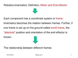
Robotics kinematics: Definition, Motor and End-effector • Each component has a coordinate system or frame. • Kinematics reduces to the relationship between the frames. • Further, if one frame is set up on the ground called world frame, the “absolute” position and orientation of the end-effector is known. The relationship between different frames = kinematics Handout 4
How to set up or assign a local frame to each component of the robot? What is called a component? What is called a joint? Handout 4
Robot Kinematics: Logics of presentation: Kinematics: what Coordinate system: way to describe motion Relation between two coordinate systems Definition of component and joint: robot structure Handout 4
World frame Handout 4
Link: Component with only considering its joint line but neglecting its detailed shape. Next slide (Fig. 2-21) shows various types of joints Handout 4
Fig. 2-21 Joint types Kinematic pair types Neglecting the details of the joint but relative motions or relative constraints between two connected links Degrees of freedom of joint: the number of relative motions between two links that are in connection Handout 4
General configuration of link Fig.2-22 Handout 4
From axis i-1 to axis i The geometrical parameters of the general link are: - The mutual perpendicular distance: a i-1 - The link twist: i-1 From axis i-1 to axis i Fig. 2-23 shows two links that are connected, which leads to the following geometrical parameters: - d i link offset - joint angle From axis a(i-1) to axis a(i) along axis i From axis a(i-1) to axis a(i) Handout 4
Fig. 2-23 Handout 4
Denavit-Hartenberg (D-H) notation for describing robot kinematic geometry. • It has the benefit that only four parameters describe completely robot kinematic geometry. The above four parameters define the geometry of Link (i-1). • The shortcoming is that the four parameters defined across two links, e.g., for Link (i-1) in the above, the four parameters are defined based on Link (1-1) and Link (i). Handout 4
Alternative way to define D-H parameters Definition of DH parameters for Link (i) will cross two links as well, that is, Link (i) and Link (i-1). In this class, we take the previous one. Handout 4
Labeling of links: towards a unified representation • The base link or ground 0. • The last link n. • For other links, 1, 2, …., n-1. Handout 4
Robot Kinematics: Logics of presentation: Kinematics: what Coordinate system: way to describe motion Relation between two coordinate systems Definition of component and joint: robot structure Assign a local frame to each link (D-H notation) Handout 4
Rule to assign a frame to each link (intermediate links) • The Z-axis of frame (i), Zi is coincident with the joint axis i. The origin of frame (i) is located at the intersection point on axis i of the common perpendicular line between axis i and axis i+1. • Xi points along the common perpendicular line between axis i and axis I+1, particularly directed from axis i to axis i+1. In the case that the common perpendicular distance is zero, Xi is normal to the plane which is spanned by axis Zi and Zi+1. • Yi is formed by the right-hand rule based on Xi and Zi. Handout 4
Fig. 2-24 An example for link i-1 and link i Handout 4
The rule for the D-H coordinates of frame (0) and frame (n): • For frame (0), the rule is as follows: • Define Z0 coincident with Z1 such that ao= 0.0. • Define X0 such that αo = 0.0. • Additionally, define the origin of frame (0) such that d1= 0.0 if joint 1 is revolute, or θ1 = 0.0 if joint 1 is prismatic. • For frame (n), the rule is as follows: • Define Xn such that αn = 0.0. • Z axes are all normal to the paper plane, including Z0. • Z0 is coincident with Z0 and Z1, so a0=0.0, α0 = 0.0. • X0 is set such that d0=0.0. • X3 is set such that d3=0. Handout 4
Summaryofthe D-H parameters • If the link frames have been attached to the links following the foregoing convention, the definitions of the link parameters are (for link i): • ai : the distance from Zi to Zi+1, measured along Xi. • di : the distance from Xi to Xi-1 measured along Zi. • αi : the angle between Zi, and Z i+1measured about Xi. • Θi : the angle between X i-1 and Xi, measured about Zi. • Remark: Choose ai> 0 since it corresponds to the distance; however, other three parameters could be a number with signs (plus, minus). Handout 4
A note about non-uniqueness in assignment of D-H frames: The convention outlined above may not result in a unique assignment of the frame to the link. There are two choices of the direction of Zi when defining Zi axis with joint axis i. When axes i and i+1 are parallel, there are multiple choices of the location of the origin for frame (i). When axes i and i+1 are in intersection, there are two choices of the direction of Xi. When Zi and Zi+1 are coincident, there are multiple choices for Xi as well as for the location of the origin of frame (0). Handout 4
Example 1 Fig.2-25 Handout 4
Fig.2-26 Link 0 Link 1 Link 2 Handout 4
Example 2 Handout 4
Summary Link and joint concept. D-H notation for link. Assign frames to links based on D-H. Benefit of D-H: a minimum number of parameters to describe links and joints. Shortcoming of D-H: parameters must cross two consecutively connected links. Handout 4
Robot Kinematics: Logics of presentation: Kinematics: what Coordinate system: way to describe motion Relation between two coordinate systems Definition of component and joint: robot structure Assign a local frame to each link (D-H notation) Kinematic equation Handout 4
Robot kinematics: The relationship among the D-H frames In the previous discussion, D-H frames are established, that is, we have 0, 1, 2, …, n frames established based on the D-H notation and rule. In this slide, we discuss the mathematical representation for this relationship. Handout 4
The goal is to find the relationship matrix for frame i-1 and frame i Handout 4
The idea is to put a series of frames between them, denoting them as FR, FQ, FP. As such, frame i-1 FR FQ FP frame i. Handout 4
The idea is to put a series of frames between them, denoting them as FR, FQ, FP. As such, frame i-1 FR FQ FP frame i. T from i-1 to FR T from FQ to FP T from FR to FQ T from FP to i Handout 4
Forward kinematics • General idea: suppose that we have n moving likes. • Solution: forward kinematics, given the motor’s motion, to find the position and orientation of the end-effector. • The position of the end-effector and the orientation of the end-effector completely describe the end-effector. • The position of the end-effector can be the position of the origin of the frame (on the end-effector). • The orientation of the end-effector is represented in the R matrix between the frame (on the end-effector) and the world frame or frame to the ground, i.e., {0}. Handout 4
The problem is: known the right side variable to find the left side variable. Handout 4
Inverse kinematics Handout 4
The problem is: known the left side variable to find the right side variable. Handout 4
Example 1 Handout 4
T matrix here Handout 4
Forward kinematics Handout 4
Inverse kinematics Handout 4
Summary Transformation matrix between two DH frames. General equations for forward kinematics. General equations for inverse kinematics. Handout 4