Utilizing XML for Detector Geometry Description in VMC Framework
220 likes | 317 Views
This paper discusses the implementation of XML for describing detector geometry in the Virtual Monte Carlo (VMC) framework. It outlines the transition from the Fortran-based macro language to a ROOT-based geometry model in STAR's simulation software. The motivation behind this migration includes retiring Geant 3.21, improving integration with new tracking systems, and facilitating detector upgrades. The advantages of using XML for geometry modeling and description are highlighted, emphasizing its industry-standard status, hierarchical structure, flexibility, validation methods, and potential for interfacing with other applications. The paper also explores the development of a structured Geometry Description using XML and references advanced schemas like AGDD and GDML.

Utilizing XML for Detector Geometry Description in VMC Framework
E N D
Presentation Transcript
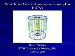
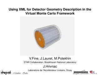
Using XML for Detector Geometry Description in the Virtual Monte Carlo Framework V.Fine, J.Lauret, M.Potekhin STAR Collaboration, Brookhaven National Laboratory J.Hrivnac Laboratoire de l'Accélérateur Linéaire, Orsay
Current Status of the Simulation Software in STAR • A set of tools based on Geant 3.21 still used in production, and nearing the end of its lifecycle. The geometry of the STAR apparatus is described in a Fortran-based macro language, and can be made persistent in the form of ZEBRA files. The code is structures ad 18 source files, each describing a subsystem. • A Virtual Monte Carlo platform (VMC), based on the ROOT system, has been created and integrated with the rest of the STAR off-line software • This new software is in the final stages of development and testing • During the transition period, both “old” and “new” simulation engines use the geometry described in the single source, in a Fortran-based macro language, with automatic translation to Root-based geometry model for the purposes of the VMC simulations • A new tracking software has been commissioned a few months ago and a large effort is under way to study its performance under a variety of conditions. It is using a geometry modeler distinct from those used in Geant and VMC simulations.
Geometry Model Visualization Simulation Geometry Modeling and Description We aim for a single geometry model and/or description (single source) in simulations, event displays and tracking Track reconstruction
Geometry Modeling and Description Motivations for migration of the simulation software, geometry model and geometry description: • Retiring Geant 3.21 is imminent, and in any case the set of tools developed within its framework does not provide for the single geometry model and description, which has been a long standing goal of the STAR software group. Resolving this will increase the transparency of the analysis, eliminate work duplication and possible coding errors and inconsistencies. • We must improve integration with the new tracking system, and employ same geometry model for it, too. • Since STAR is pursuing a vigorous program of detector upgrades, having efficient detector development, rapid prototyping, simulation and visualization tools becomes a necessity.
Geometry Modeling and Description Geometry model refers to a memory resident data structures representing the detector’s configuration, which are used by an application. The ROOT-based geometry (i.e. an assembly of objects based on the ROOT classes specifically designed for geometry modeling) is a natural choice for a STAR application because of the heavy use of ROOT in most software systems created and run by our experiment. Geometry description is a human–readable (and often human-created) document, which serves as source code for the creation of the geometry model at run-time.
Geometry Modeling and Description We have a few choices for the Geometry Description implementation, such as • Root C++ code (or “cint” macros) • pros: • language already exists and is familiar to users • cons: • in a large-scale experiment, there is a large possibility of writing obscure and inaccessible code • no code validation tools exist, i.e. one has to compile and load to validate anything • code written as in C++ will remain largely non-portable to other systems, although this is mitigated by exporting the Root geometry to GDML (a particular XML schema) and using it as an exchange format • limited choice of Geometry Visualization tools • A different, and preferably platform-neutral language that can be parsed into the Root format and also accessed by other applications and platforms.
Geometry Modeling and Description We have elected the second approach in pursuing a structured Geometry Description (as opposed to free-form C++), with XML as the basis of the language platform, in view of the following advantages: • XML being the industry standard with large number of both commercial and user-supported tools, such as highly advanced editors which assist the user in writing and validating the code • Hierarchical structure of the XML document naturally maps onto the application realm of the geometry model • Flexibility to create a schema that is best suited for the application • Facilitates interaction with the database (standard approaches and products exist) • Validation: standard XML-driven methods of enforcing the rules and verifying that the code is well-formed , before the application is even run • Opens a possibility to interface with other applications (e.g. CAD and visualization), with a suitable XML transform
Geometry Modeling and Description Having chosen XML, we had an option of developing a XML schema from scratch, or using the experience, and hopefully some code, of other groups. We have studied the merits of the following advanced schemas and associated tools • AGDD – Atlas Generic Detector Description • GDML – Generic Detector Modeling Language (offshoot of Geant 4) • CMS DDD Based on factors that included accessibility of the code, possible level of interest and cooperation by the authors, and most importantly the feature set, we had chosen the AGDD as the basis for our development effort.
Geometry Modeling and Description The AGDD features: • Full set of objects to describe solid shapes, suitable for any simulation setup • Hierarchical organization of the XML geometry code, with objects being grouped and nested, which maps well onto geometry models in most Monte Carlo systems • Support for variables, one- and two-dimensional arrays for numerical data storage • Support for arithmetic calculations and certain functions (done at parse-time). Issue of numerical accuracy can be addressed, if needed. • Variety of multiple positioning operators that greatly facilitate the creation of complex geometries • Forthcoming support of boolean operations • Bona fide iterator facility (“for” loop), which again allows the developer to create complex, parameterized structures • Support for Xinclude, which allows for optimal source code sectioning and organization, and aids in versioning.
Geometry Modeling and Description Accompanying product for the AGDD schema: an advanced graphics viewer known as GraXML (credit: J.Hrivnac). Allows full visualization of AGDD-compliant geometry source files in XML format. Color Adjustment sliders Image manipulation tools Main Viewer Pane Volume selection and navigation pane Interactive command window
Geometry Modeling and Description Now that we have chosen a schema, how so we translate a compliant XML document into the ROOT geometry model? Choices: • Parse the XML in C++ and create a geometry model inside a Root application – (SAX, DOM?) • Adopt and reuse the JAXB parsing technology from the GraXML viewer. Advantages: • JAXB parser creates a model of the document which consists of typed objects, with the XML schema serving as the object declaration tool. This is in contrast with DOM parsers which simply create hierarchies of containers of string data and thus need significant amount of additional logic to correctly • a proven parser with immediate visualization We have opted to reuse GraXML and to develop the necessary additional classes that are necessary in order to create the ROOT geometry. In this approach, we essentially have created a C++ code generator driven by XML input.
Geometry Modeling and Description The GraXML is a Java application. It parses the XML input and in doing so creates the so called Generic model, which is a tree of typed objects (not just containers) representing the input data according to the user-supplied schema (in the this case, AGDD). The tree is then traversed in order to inflate a geometric model that can be readily visualized. The visualization layer is based on the Java3D graphics library. The traversal process can also be used to construct other types of object, such as C++ graphics objects. This can be done in-memory, or by generating the C++ source code as output.
Tree Traversal Geometry Parsing and Code Generation JAXB parser Generic Model XML geometry source Visualization Root C++
An Example: a R&D XML code sample Variables and arrays <?xml version="1.0" encoding="UTF-8"?><AGDD DTD_version = "v7" xmlns:xi="http://www.w3.org/2001/XInclude"> <xi:include href="StandardMedia.xml"/><xi:include href="StandardMaterials.xml"/> <section DTD_version = "v7" name="HFT" version="$Id: $" date=“01/15/05" author="M.Potekhin" top_volume="TEST"> <var name="Rin" value="1.45" /> <var name="Rout" value="5.65" /> <var name="TotLength" value="16.0" /> <var name="LadderWidth" value="2.00" /> <var name="LadderThk" value="0.002" /> <array name="r“ values="5.294; 4.862; 4.391;1.595" /> <array name="a" values="0.0; 20.27;42.62;79.51“/> <array name="aOffset" values="89.28; 88.31; 87.01; 70.15" /> <box name="cave" medium="active" X_Y_Z="10; 10; 50" unit_length="cm" /> <tubs name="pxmo" medium="active" Rio_Z="Rin; Rout; TotLength" unit_length="cm" /> <tubs name="psec" medium="active" Rio_Z="Rin; Rout; TotLength" profile="-11;118" unit_length="cm"/> <box name="plmo" medium="active" X_Y_Z="LadderWidth; LadderThk; TotLength" unit_length="cm" /> <composition name="PSEC" envelope="psec"> <foreach index="nlad" begin="0" loops="4"> <posRPhiZ R_Phi_Z="r[nlad];a[nlad];0" rot="0;0;-aOffset[nlad]" unit_length="cm"> <volume name="plmo" /> </posRPhiZ> </foreach> </composition> <composition name="PXMO" envelope="pxmo"> <mposPhi ncopy="6" Phi0="0" dPhi="360/6" R_Z="0;0" impliedRot="true" unit_length="cm"> <volume name="PSEC" /> </mposPhi> </composition> <composition name="TEST" envelope="cave"> <posXYZ X_Y_Z=" 0; 0; 0" unit_length="cm"> <volume name="PXMO" /> </posXYZ> </composition> </section> </AGDD> Parameterization Loop Multiple positioning operator (6 copies) Nesting of Volumes
Using IDE tools in XML development Some helpful features of the editor, Altova XMLSpy (same code sample as above) Validation against the schema at any time Attributes of the current tag Choice of views of the XML document
Am example: a R&D XML code sample Continued from the previous page: visualization of the XML geometry code for the proposed new central tracker in STAR, with complex positioning of the silicon sensors
An Example: generated C++ code sample Continued: the ROOT C++ code produced by the parser. A small snippet presented due to screen size limitations. TGeoCombiTrans* ct_plmo21 = new TGeoCombiTrans(); psec->AddNode(plmo,21,ct_plmo21); ct_plmo21->RotateX(0.0); ct_plmo21->RotateY(0.0); ct_plmo21->RotateZ(-89.28); ct_plmo21->SetTranslation(0.53,0.0,0.0); TGeoCombiTrans* ct_plmo22 = new TGeoCombiTrans(); psec->AddNode(plmo,22,ct_plmo22); ct_plmo22->RotateX(0.0); ct_plmo22->RotateY(0.0); ct_plmo22->RotateZ(-68.04); ct_plmo22->SetTranslation(0.46,0.17,0.0); TGeoCombiTrans* ct_plmo23 = new TGeoCombiTrans(); psec->AddNode(plmo,23,ct_plmo23); ct_plmo23->RotateX(0.0); ct_plmo23->RotateY(0.0); ct_plmo23->RotateZ(-44.39); ct_plmo23->SetTranslation(0.32,0.3,0.0); TGeoCombiTrans* ct_plmo24 = new TGeoCombiTrans(); psec->AddNode(plmo,24,ct_plmo24); ct_plmo24->RotateX(0.0); ct_plmo24->RotateY(0.0); ct_plmo24->RotateZ(9.36); ct_plmo24->SetTranslation(0.03,0.16,0.0);
An example: a R&D XML code sample Question: How do we verify the C++ code generated by our parser is valid? Answer: We use the STAR-developed ROOT geometry browser (credit: V.Fine) Below: See the visualization of the generated C++ code for the same assembly of silicon sensors. (There was only one light source used in this rendering)
Example: validation of the XML to C++ conversion The TGeo browser developed in STAR is a valuable geometry development and visualization tool, which is also useful in validation of the XML to ROOT C++ transformation Compare: visualization of XML in GraXML (left) vs the generated C++ code in TGeo browser (right)
Current Status of the STAR VMC The STAR VMC employs the ROOT classes for geometry modeling and navigation. As such, it can use the following to input the geometry description: • a root file • a piece of C++ code (cint macro) Since we don’t have a detailed XML model of the STAR detector yet, an automatic conversion procedure is used to build a ROOT geometry based on the ZEBRA data structures saved from GEANT 3.21, thus allowing us to continue development and testing. This means that the primary source if still in Fortran and this therefore is a temporary solution. Once the work on the XML-based geometry description is complete, we shall start a migration to the new system.
Conclusion Project Status: • We have chosen a suitable XML schema as the method to describe the geometry of the STAR detector • We have developed a Virtual Monte Carlo application which uses ROOT classes to model geometry • We have developed a parser-converter, which generates the ROOT C++ geometry code from XML input Action Items: • Finalizing the XML schema • Improving the visualization tools • Having a group of beta-testers start coding up the detailed geometry of select STAR systems • Developing the remaining elements and interfaces of the STAR Virtual Monte Carlo, which will allow a complete operation with the XML-based geometry, and subsequently a complete transition of the STAR Collaboration to VMC.