Download
1 / 20
250 likes | 564 Views
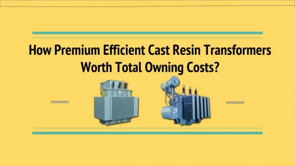
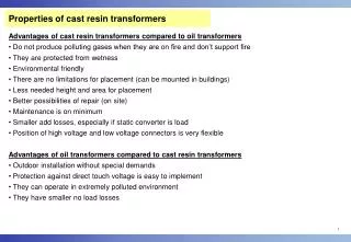
Properties of cast resin transformers. Advantages of cast resin transformers compared to oil transformers Do not produce polluting gases when they are on fire and don’t support fire They are protected from wetness Environmental friendly

E N D
Properties of cast resin transformers • Advantages of cast resin transformers compared to oil transformers • Do not produce polluting gases when they are on fire and don’t support fire • They are protected from wetness • Environmental friendly • There are no limitations for placement (can be mounted in buildings) • Less needed height and area for placement • Better possibilities of repair (on site) • Maintenance is on minimum • Smaller add losses, especially if static converter is load • Position of high voltage and low voltage connectors is very flexible • Advantages of oil transformers compared to cast resin transformers • Outdoor installation without special demands • Protection against direct touch voltage is easy to implement • They can operate in extremely polluted environment • They have smaller no load losses
Fans Range of rated powers and voltages Range of rated power: 50 kVA – 40 MVA Upper value of rated voltage: 36 kV 4.8 m length, 2.8 m width, 4.7 m height Transformer of rated power 40 MVA (the biggest manufactured transformer till now)
Low voltage connectors Core Spacers Low voltage winding High voltage winding High voltage connectors Cast-resin Transformer construction Low voltage winding: Folio winding type High voltage winding: Disc type
Construction versions(according to our experience): • Core – without cooling channels or with one cooling channel in the middle of core • Standard construction is following radial disposition: • core – folio (LV) winding – disc (HV) winding. • There are also other constructions (radial dispositions of the windings): • folio-folio-disc, disc-disc, folio-folio-folio. • Further in presentation, standard configuration will be considered. • Software for thermal design has been made only forstandard configuration, • but it can be extended to all other configurations. • Insulation cylinder between core and low voltage winding (folio): 0, 1 or 2 cylinders • Low voltage winding (folio) build from 1, 2, 3, 4 or 5 parts (up to 4 cooling channels); • if there is more than one part, „dog bones“ spacers are used for forming cooling ducts • Insulation cylinder between low voltage winding (folio) and high voltage winding (disc): • without, only in middle phase or in all tree phases • High voltage winding (disc) made of 1, 2 or 3 parts (up to 2 cooling channels)
Checking of guarantee values of temperatures with heat run test • Standards (IEC 60076–11, 2004) predicts tree possibilities for loading and heating oftransformer: • Simulated load method • Back to back method • Direct loading method • Minimum equipment is needed for Simulated load method. • There is two parts of test, and each of them last until steady state is reached: • Heating with no load losses, with rated losses in core (e will be designation for winding temperature rise measured in steady state) • Heating in short circuit test, with rated current (cwill be designation for winding temperature rise measured in steady state)
From previously measured two temperature rises, value of temperature rise when transformer is normally loaded is calculated (c‘), witch is guaranteed value: K1 = 0.8 for natural air flow K1 = 0.9 for forced air flow Example: Transformer of rated power 630 kVA, for rated voltage 15000 V / 420 V Heating in open circuit test (duration 16 hours): – Core temperature rise 49.7 K – LV winding temperature rise 24.1 K – HV winding temperature rise 5.0 K Heating in short circuit test (duration 18 hours): – Core temperature rise 30.8 K – LV winding temperature rise 72.5 K – HV winding temperature rise 75.7 K Calculated temperature rises when transformer is normally rated loaded – Temperature rise of LV winding 87K – Temperature rise of HV winding 78K Rises are less then permissible 100K (class F, supposed ambient temperature 40°C)
Physic of heat transfer from active parts of transformer • Example: • Standard configuration • Core without cooling channels • Folio winding in one part • Disc winding in one part • Without insulation cylinders • General principles: • AN cooling of surfaces • Radiation heat exchange between opposed surfaces • In active parts between cooling channels there is conduction heat transfer with distributed heat generation
Components of mathematical model: • Energy balance equations • Equations of boundary conditions (on boundary surfaces to air) • Equations of conduction heat transfer in parts between cooling channels A. Example of equation of energy balance for low voltage and high voltage windings Radiation from core LV winding Generated heat because losses in winding Convection from inner part of winding Radiation from LV to HV winding Convection from outer part of winding HV winding Radiation from HV winding to ambient
B: Equations of boundary conditions (on boundary surfaces to air) Example for nonsymmetrically heated channel B1. Convection z – height coordinate, b – width of axial ccoling duct Entry region((z)60) Fully developed region((z)60) b – width of channel HW – height of winding Outer surface Inner surface
B2. Radiation Between concentric cylinders Between half-cylinders of neighbor phases F12–view factor, describing influence of neighbor phase From half-cylinder radiated to free space (outer phases) Horizontal cross-section
Implementation of mathematical method in the software (radiation heat exchange betweencylinders of neighbor phases) Coordinates of points B‘, B‘‘ i C are described analytically by using theory of analytical geometry
max 1 2 qv qS2 qS1 x* d C. Equations of conduction heat transfer in parts between cooling channels Thermal resistance of insulation between two layers Pi Losses in one layer 1, 2 Temperatures of inner and outer surfaces Temperature1 depends on Pleft (boundary condition: convection and radiation); 2depends on Pright
Average temperature of winding Example for the case of low voltage winding with no cooling channels in the winding:
Size and characteristic of complete mathematical model System in nonlinear and there is big degree of mutual correlation of exposed components of mathematical model. Because of that the complete model contains large number of nonlinear equations. For example, if there is cylinder between LV and HV winding, there would be 13 equations: 1 for outer surface of core 5 for LV winding 2 for cylinder between LV and HV winding 5 for HV winding Unknowns in system of 13 equations: 11 temperatures: - outer surface of core, - outer and inner surface of: - cylinder carrying LV winding - insulation over LV winding - cylinder between LV and HV winding - inner layer of cast resin of HV winding - outer layer of cast resin of HV winding 2 radial positions of hot-spots (in LV and HV winding)
Realized software for thermal design • Software is done by using and connecting Excel + Mathcad programming tools. • Mathcad is used for solving complex system of nonlinear equations • Excel is used as input and output user interface • One Excel sheet is used as input sheet for construction data about transformer • Other sheet contains results of calculation of characteristic temperatures • It is possible to enter data from heat run test, and make database with compared measured and calculated values of temperatures • Results of this database can be used as basis for increase of accuracy of calculation methods, i.e. for fine tuning of coefficients (for example those in formulas on slide 10).
Input Excel sheet / illustration on parts of sheets with construction data and characteristics of materials
Input Excel sheet / Illustration on part of table with data about HV winding and losses in HV winding Input Excel sheet / Data from heat run test
Excel sheet of results / Part of table with calculated characteristic temperature rises Illustration of connection between Excel and Mathcad
Illustration of Mathcad program / • Part of program with air parameters • Part of program for parameterization of calculation • Part of program with initial iteration • Part of program with basic functional dependencies
Illustration of Mathcad program / • Part of program that contains equation system • (for illustrated tree equations it is visible only one forth of them)