Download
1 / 25
250 likes | 411 Views
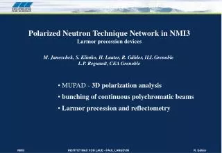
Polarized Neutron Technique Network in NMI3 Larmor precession devices M. Janoschek, S. Klimko, H. Lauter, R. Gähler, ILL Grenoble L.P. Regnault, CEA Grenoble. MUPAD - 3D polarization analysis bunching of continuous polychromatic beams Larmor precession and reflectometry.

E N D
Polarized Neutron Technique Network in NMI3 Larmor precession devices M. Janoschek, S. Klimko, H. Lauter, R. Gähler, ILL Grenoble L.P. Regnault, CEA Grenoble • MUPAD - 3D polarization analysis • bunching of continuous polychromatic beams • Larmor precession and reflectometry
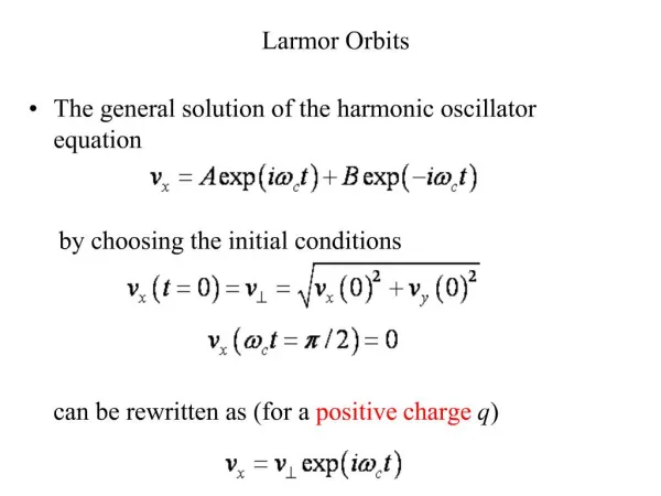
A) Conventional magnetic scattering: Intensities from nuclear Bragg peaks: Inuclear N*k Nk; NkFT{nuclear(r)}; Intensities from magnetic Bragg peaks: ImagneticM*k Mk; M k k s(k) k ; s(k) FT{magnetic(r)}; magnetic structure factor Iinter[N*k Mk+ M*k Nk] Pi; Higher visibility of magnetic(r) by nucl.-magn. Interf.: Iinter depends on direction of incom. Polarisation Pi to magn. interaction vector Mk The component of Mkalong Pi is measured.
B) Spherical neutron polarimetry Blume (1963) : calculation of polarisation Pf(Pi) for magnetic + nuclear scattering: Pf= N*k NkPi - M*k Mk Pi + M*k ( Pi Mk ) + ( Pi M*k ) M k + N*k Mk+ M*k Nk - i [ N*k Mk- Nk M*k] Pi Measuring direction and magnitude of Pf for few reflexes as function of of Pi is avery efficient way to determine magnitude and direction of Mk . This method requires B = 0 at the sample! In practice, complete information on Mk is obtained from measuring 3 orthogonal components of Pffor 3 orthogonal components of Pi
Cryopad principle top view field free area B 5 mG two Meissner shields nutator ki precession fields nutator secondary coil primary coil kf
Mupad, 3-coil version zi coupling-coil in zi i yi i-coil xi zi yi i sample the action of each coil is shown downstream of it ! No spin turn on scattering is assumed in the drawing ! xi i -coil Field free area 2 zf f = i - 2 yf xf f f f -coil f-coil zi zf coupling-coil out field direction yf zf Neutron spin Assume spin turns on scattering: by s in the scattering plane set f -coil to f =- i - s+2 by s with respect to z-axis set f-coil to f = - i - s yf xf
MUPAD: general setup side view top view opening for cryostat mu-metal links between cylinders and coupling screens outer mu-metal-screen inner mu-metal -screen;optional; B 5 mG ki B 5 mG -coil mu-metal shield around all coils to guide return fields in low-field region -coil; DC-compensation of mean vertical component of earth field; likely superfluous kf coupling-coil;
Design of new coils, goal: outer field integral < 1/1000 of inner field integral How to avoid field from current Iz? Al frame anodized Cu contacts for return field Iret Open area 40 x 40 Al foil for return current Al wire 1 Iz Mu metal yoke Mu metal screen Outer dimensions: 118 x 118 x 60 demagnetisation coils for all mu-metal screens!
Mupad for 2D- analysis top view He3 spin filter in -coil -coil in -coil -coil ki cryostat - -coil; return field for -coil coupling-coil kf kf Mu metal for return field
Bunching of continuous polychromatic polarized beams without loss of intensity
MIEZE - Principle L1 L2 Coherent frequency splitting Coherent reversal of frequency splitting d 0 + (s - e) e s total energy k + e/v; 0 + e + s + e plane of detection E0 i(kx - 0t) e 0 = - e k0 - e/v; 0 - e 0 - (s - e) +i(keL1 - ksL2) -i(s - e)t ke = e/v; e e 0 -i(keL1 - ksL2) +i(s - e)t ks = (s -e)/v; e e = For eL1 = (s -e)L2 , gets independent from v. beats in time with d= (s -e) detector detector
MIEZE (without bunching!) using transmitted and reflected beam after analyser L1 L2 Ce Cs B-field spin down A B = 0 P d fast detectors d e analyzer s spin up B coupling coil Idet IB IA 1 IA = 1/2[cos d·td +1], IB = 1/2[cos (d·td +)+1], with IB + IA = 1; td: time of arrival at A d = 2(s - e). time T
II) MIEZE setup with bunching using the full beam replace analyzing mirror by RF-coil (resonance frequency F=2B; -condition ) E T/2 in arrival time for spin up and spin down at the detector. E = E·T/t v3 ·T(like in spin echo); T is fairly constant for a velocity band of 5-10%. + + - L1 L2 fast detector Ce Cs B-field P B = 0 d s e RF-field; F Signal function after bunching buncher: sequence of high-field-RF-flippers Idet 1 EF = 8B EF = -8B T time
Estimate of the necessary energy chances ffor bunching: Intensity Signal function after bunching Necessary condition for overlap of both signals: = f L2 / (mv3) with /4 = D 1 f : change of energy by the bunching flipper For L=10m; =10Å; D = 2 1 MHz: f = 0.8 10-8 eV; f = 2 B; = 6.8 10-8 eV/T T time I = cos2Dt I = sin2Dt I = cos2(Dt - /4) = sin2(Dt + /4)
Quantum-mechanical view of bunching; there is no classical view of it! The variation of k = k1 - k2 due to f is not cancelled by the MIEZE condition and leads to an extra phase difference d between both waves at the detector. 2+f 1+f f 2 1 -f This determines f as before. 2-f 1-f State behind the bunching flipper: [ = (s - e)t] sin (+d) k1 k2 k cos (-d) k1 - k2 depends on f !
Application of bunching • MIEZE at SANS instruments (no analyzer near sample) • SPAN-like NRSE spectrometer with very high resolution?
3) Larmor precession and reflectometry using ZETA at IN3 A) Off-specular scattering from polymer-multilayer B) Larmor pseudo-precession in reflection
Mono SEU1 sample* SEU2 Ana Det (CCD camera) Lf ki = 2.44 Å Li Lfr Lfy Lenghts Lf depend to first order on scattering angle; ‘angular encoding’ Rf flippers arranged symmetrically w.r.t. ki