Download
1 / 20
200 likes | 302 Views
Deformation of Mawrth Landing Ellipse Bedrock Due to the Oyama Impact Dawn Y. Sumner, Geology, UCDavis. 1: Impact Predictions Age of the Mawrth Area Bedrock Cratering Rates at 4.0-3.8 Ga II : Predicted Deformation From the Oyama Impact Senft & Stewart (2009) Models for Deformation

E N D
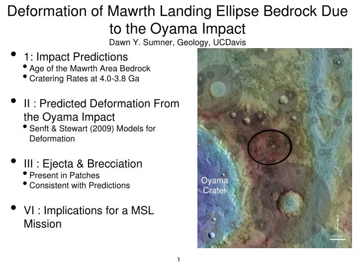
Deformation of Mawrth Landing Ellipse Bedrock Due to the Oyama ImpactDawn Y. Sumner, Geology, UCDavis • 1: Impact Predictions • Age of the Mawrth Area Bedrock • Cratering Rates at 4.0-3.8 Ga • II : Predicted Deformation From the Oyama Impact • Senft & Stewart (2009) Models for Deformation • III : Ejecta & Brecciation • Present in Patches • Consistent with Predictions • VI : Implications for a MSL Mission Oyama Crater
Age of Mawrth Bedrock & Cratering Rates Saturation Dawn’s Extrapolation • Rocks are Broken by Stress, not Age, except that a greater age provides more opportunities for disruption and >3.5 Gy there were many more impacts. • Age of Mawrth Bedrock • Crater Counts: Early to Late Noachian Michalski and Noe Dobrea, 2007, Geology • Mineralogy Model: Phyllosian, e.g. Early to Mid-Noachian Bibring et al., 2006, Science • Craters per 300 km2 (~ellipse size) • 300 d≥250 m Craters at Saturation • 12 - 50 d≥500 m Craters 3.8 Gy - Saturation • 1 - 12 d≥1 km Craters 3.8 - 4.0 Gy • 0.1 - 1 d≥4 km Craters 3.8 - 4.0 Gy Noachian Boundary (Tanaka, 1986) Hartmann & Neukum 2001
Predicted Crater Distributions • Craters • 1x 4 km Diameter • 6x 1 km Diameter • 24x 500 m Diameter • 269x 250 m Diameter • Color Scheme • Dark Blue = Crater • Medium Blue = +1 Radius • Light Blue = +1 Diameter • (damage extensive in 1 radius, • present in 1 diameter) Area of Circle = 300 km2 4 km
Observed vs Predicted Crater Distribution Need significant deflation to remove effects even if crater not observed since have brecciation to at least 1 radius depth
Damage Predicted in the Mawrth Ellipse • Grey Circles: 2 radii beyond crater rim • Real Problem: Proximity to Oyama Crater • Oyama Crater • Younger Than Landing Ellipse Bedrock • ~100 km in Diameter • Ellipse Edge: ~8 km From Rim
Deformation from 1-2 Radii Beyond Crater Rim Crater Rim 1 Radius Deformation at Free Surface Collins et al. 2004 The pattern of deformation in this image is ubiquitous air gun experiments, computational models, and natural craters. The formation of “feathery” fractures near the surface for substantial distances is a fundamental response of rock-like rheologies to the shock and surface waves produced by impact. Total Plastic Shear Strain
Mawrth & Oyama Crater Edge of Mawrth Ellipse 0 km • Cratering model of 100 km diameter craters • Simulations of Impact Strain Predict Extensive Bedrock Damage (Senft & Stewart 2009, EPSL) • Models appropriate for a similar crater size on any rocky planet “In general the gross level of structural deformation will be similar around any similar size crater on any rocky planet. The scaling to different gravities was done in the impact conditions that made that size crater. A primary difference between Earth and Mars is the different mean impact velocities -- ~20 km/s for asteroids hitting Earth; ~5 km/s for asteroids hitting Mars. As a result, there is less impact (silicate) melt generated on Mars for the same size crater. However, the shock pressures (and hence the deformation) in the rock around the crater rim is similar in both cases.” - Sarah Stewart, pers. comm. 11 May 2011 60 0 60 km Brecciated to >1 km depth at ellipse distance (Shear strain of 1.0 = a square sheared to a parallelogram with a corner angle of 45°.)
Movie of Deformation - 100 km Final CraterNote: movie does not show the final crater morphology; crater collapse continues for 100’s sec Edge of Mawrth Ellipse
Movie of Deformation – ~150 km Crater Modeled Crater: Peak Ring at r=40 km, Outer Ring at r~70 km Shear Strain of 5 to 1 km depth beyond Outer Ring Grey: Sediment Tan: Crust Brown: Mantle (Shear strain of 5.0 = a square sheared to a parallelogram with a corner angle of 11°.)
Implications For the Mawrth Ellipse 20° x 20° Area of Circle = 300 km2 Extensive Brecciation Expected 4 km (and observed - see Sumner’s Mawrth presentation for the Sept. 2010 Landing Site Workshop)
The following slides document secondary craters and ejecta near and in the Mawrth ellipse, demonstrating: 1. The bedrock is older than Oyama Crater.2. The >1 km of highly fractured rock has not been eroded away.Please see Sumner, 2010, Workshop #4 Presentation for Documentation of Brecciation of the bedrock in the Mawrth Landing Ellipse Physical Outcrop Characteristics of the Mawrth Candidate Landing Site & the Potential Role of Impacts in Shaping Stratigraphyhttp://marsoweb.nas.nasa.gov/landingsites/msl/workshops/4th_workshop/program.html
The Continuous or Primary Ejecta Facies from Oyama Crater should, at one time, have covered the area shown here. Remnants remain. Page numbers and white boxes indicate the location of pictures shown on subsequent pages/slides. p. 17 (area in large box not shown) Subsequent Anaglyphs p. 18 (Old Ellipse) Next Slides Oyama Crater rim (Images & interpretations courtesy of Ken Edgett) mosaic of CTX images
Chain of dark buttes interpreted as the remains of Oyama secondary craters (differential erosion has put them up on “pedestals”). See next slide for a zoomed-in view of two of these… 3-D (Images & interpretations courtesy of Ken Edgett) HiRISE PSP_010882_2040 & PSP_010816_2040
Close-up of the remains of two (proposed) Oyama secondary craters. These secondaries would likely have been above some of the crater’s continuous ejecta deposit, but might themselves have also been buried within it. Ejecta Clasts? 3-D HiRISE PSP_010882_2040 & PSP_010816_2040 (Images & interpretations courtesy of Ken Edgett)
Sanjeev Gupta’s Independent Evaluation of These Features: Chain of Secondary Impacts from Oyama Note upturned rim of mesa These were proposed as a « fluvial » target for MSL, but Sanjeev, Ken and I see no evidence of fluvial activity. ~100 m (Images & interpretations courtesy of Sanjeev Gupta)
Topographic Profile Across Mesa on Previous Page Across axis Along axis (Noe-Dobrea et al 4th MSL Workshop 2010) (Images & interpretations courtesy of Sanjeev Gupta)
Possible Remnants of the Oyama Continuous “Ejecta” Facies from the candidate MSL landing ellipse Much of Oyama’s continuous ejecta facies—which would include both material ejected from the crater and material ripped up from the surrounding terrain—has been eroded away. However, patches of ejecta are still present. These dark, rugged hills are tentatively interpreted as ejecta remnants. 3-D Large, angular clasts in mound of dark, rough material PSP_006676_2045 & PSP_007612_2045 (Images & interpretations courtesy of Ken Edgett)
Ejecta Remnants and Damage (brecciation) to the substrate 3-D large angular clasts + dark matrix elevated relative to substrate large light-toned clasts in dark material superposed on fractured, light-toned substrate (Images & interpretations courtesy of Ken Edgett) HiRISE PSP_006676_2045 & PSP_007612_2045
Slide on Right ~30 km from Edge of Oyama Crater Please see Sumner, 2010, Workshop #4 Presentation for Documentation of Brecciation of the bedrock in the Mawrth Landing Ellipse Physical Outcrop Characteristics of the Mawrth Candidate Landing Site & the Potential Role of Impacts in Shaping Stratigraphy http://marsoweb.nas.nasa.gov/landingsites/msl/workshops/4th_workshop/program.html
Edge of Mawrth Ellipse Conclusion: 0 km • A mission at the currently defined Mawrth ellipse would be predominantly an investigation of the effects of the Oyama impact on pre-existing bedrock. 60 0 60 km This is a very unfortunate result, as I set out in search of evidence that would refine interpretations of a sedimentary environment. It would have been nice to find evidence of an old sedimentary environments with diverse hydrous minerals that are easily accessible to MSL at Mawrth. However, I do not see evidence for sedimentary deposits that preserve evidence of habitatibility even though I have evaluated HiRISE or CTX images in detail at each location near the landing ellipse where such evidence has been proposed in the literature or at a landing site workshop.