Multi-Stage Flash Desalination (MSF)
Multi-Stage Flash Desalination (MSF). Lec . 8. Introduction. The MSF desalination process was introduced in the early 1950 s.


Multi-Stage Flash Desalination (MSF)
E N D
Presentation Transcript
Introduction • The MSF desalination process was introduced in the early 1950 s. • In 1957 The process, the number of flashing stages and the heat transfer area were optimised . Since then, the MSF process has gone through several dramatic modifications and improvements, which have lead to a massive increase in unit capacity, from 500 m3/day in the 1960 s to 75,000 m3/day in the 1990 s. • Other developments include the use of demistersin all flashing stages, which limits entrainment rates of brine by the flashed-off vapour. • As a result, product salinity is maintained below 10 ppm. • Also, development of the on-line ball cleaning system has resulted in less frequent use of acid cleaning and plant shutdown. • Currently, MSF plants can be operated for periods varying from 2 to 5 years before a major overhaul (service) is necessary. • Recent field experience shows that a large number of old MSF plants are being rehabilitated (restore) to improve performance and extend service life. Dr. Ola Abdelwahab
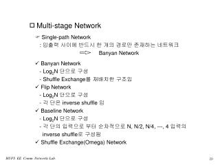
MSF- Flashing Chamber • The main element in the MSF process is the flashing chamber. • A schematic diagram of the MSF flashing stage is shown in Fig. 1 and includes the following items. 1. A large brine pool with a similar width and length to the flashing stage and with a depth of 0.2–0.5 m. 2. A brine transfer device, comprising a weir and splash plate combination between the stages, is designed to seal the vapour space between the stages and to enhance turbulence and mixing of the inlet brine stream. Dr. Ola Abdelwahab
MSF- Flashing Chamber • 3. A demister formed of wire mesh layers and supporting system. • The demister function is to remove the entrained brine droplets from the flashed-off vapour. This is essential to prevent an increase in the salinity of the product water and scale formation on the outer surface of the condenser tubes. • 4. A tube bundle of condenser/pre-heater tubes, where the flashed-off vapour condenses on the outer surface of the tubes. The released latent heat of condensation results in heating of the brine recycle stream flowing inside the tubes. • This energy recovery is essential to maintain high system performance. • 5. A distillate tray, where the condensed distillate product is collected and cascades through the stages. The distillate product is withdrawn from the tray in the last stage. Dr. Ola Abdelwahab
MSF- Flashing Chamber • 6. Connections for the venting system, which remove non-condensable gases (O2, N2 and CO2), which are dissolved in the feed seawater, even after de-aeration. • CO2 can also be generated during decomposition of bicarbonate compounds in the high temperature stages. • Another major source of non-condensable gases is air in-leakage from the ambient surroundings into flashing stages operating at temperatures below 100°C, which correspond to vacuum conditions. • 7. Instrumentation, which includes thermocouples, a level sensor and a conductivity meter, is placed in the first and last flashing stages. • The data measured at these stages is used by the process control system. Accordingly, and subject to disturbances in the system parameters, i.e. feed seawater temperature, increase in fouling thermal resistance, available steam, etc., adjustments are made in the controllers to maintain the desired operating conditions. • The magnitude of these adjustments depends on the measurements made in the first and last stages. Dr. Ola Abdelwahab
MSF flashing chamber Dr. Ola Abdelwahab
MSF Processes • There are two main layouts for the MSF process. • the once-through system and • the brine circulation system. • The brine circulation system is to be found on a larger scale than the once-through system. • Figure 3 shows a schematic for the MSF once-through process. Dr. Ola Abdelwahab
Once-through multi-stage flash process Dr. Ola Abdelwahab
Once-through multi-stage flash process Dr. Ola Abdelwahab
Process Description • In the MSF- OT process the separation is achieved by evaporating some of the feed in each stage by flashing. • the hot feed seawater entering each stage encounters a lower pressure than its own vapour pressure; it then flashes off producing vapour on one side and so cooling the brine flowing on the other side. • This results in a decrease in brine temperature and an increase in its salinity, stage by stage. • Such a flashing process is repeated, stage after stage, due to the continuous decrease in stage pressure, afforded by the drops in pressure of the brine flowing through the brine orifices. • Vapour produced at each stage passes through a demister, thus dramatically reducing the entrainment of brine droplets, and condenses on the external surface of the tube bundle. Dr. Ola Abdelwahab
Process Description • Latent heat of condensation is transferred to the feed seawater, which flows through the condenser tubes from stage n to stage 1. • The feed seawater temperature increases upon condensation of the flashed-off vapour on the outside surface of the condenser tubes. • A further increase in the temperature of feed seawater exiting from the 1st stage condensing tubes takes place in the brine heater. • Here, heating takes place by the use of saturated steam, which is usually extracted from the low pressure turbines of a power generation system. Dr. Ola Abdelwahab
Brine circulation multi-stage flash process Dr. Ola Abdelwahab
Brine circulation multi-stage flash process • The purpose of brine recirculation is to decrease the flow rate of the feed seawater. • As a result, this lowers the chemical additive consumption rate and the size of the pretreatment facilities for the feed stream. • Also, since the recycled brine contains higher energy than the feed seawater, the process thermal efficiency will improve. • The simplest brine circulation system is made through mixing part of the blow-down brine with the feed stream. • This simple configuration is shown in Fig. 5. • In this system, a portion of the blow-down brine, is mixed with the intake seawater stream, Mf. • The resulting mixture, has a higher salinity and temperature than the intake seawater. • The remaining elements of the system are similar to those of the once through MSF. Dr. Ola Abdelwahab
Brine circulation multi-stage flash process • De-aeration of the feed seawater is an essential element in the MSF brine circulation system. • It removes dissolved gases from the feed stream, i.e. oxygen, nitrogen, and carbon dioxide. If these gases are not removed, they will be released in the flashing stages. • The released gases have low thermal conductivity and would reduce the heat transfer rate around the condenser tubes. Carbon dioxide and oxygen may also promote corrosion reactions in various locations in the flashing stages. • The de-aerator may have a vertical or horizontal configuration equipped with spray nozzles or trays. • De-aeration is performed by heating steam, which results in an increase in the feed temperature and as a result reduces gas solubility in the feed water. Dr. Ola Abdelwahab
Self- Study Topics • Tube materials used in pre-heater of MSF desalination (Report). • Process description of MSF desalination with thermal vapor compression (Presentation). Dr. Ola Abdelwahab