Download

1 / 27
270 likes | 410 Views
This document details the objectives and methodologies of the NA60 experiment at CERN, focusing on Ultra-Peripheral Indium-Indium (In-In) collisions. It highlights the sophisticated detection setup, including MWPCs, trigger hodoscopes, and magnet configurations, which are critical for measuring the mass distribution of VT dimuons produced in these collisions. The text also outlines the event selection criteria, background management, and the role of various detectors like the ZDC and Quartz Blade in gathering data while minimizing beam and interaction pileup.

E N D
UPC in NA60 Jornadas LIP 2008 – Pedro Ramalhete
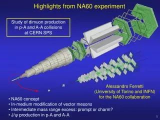
NA60 @ CERN 8 MWPCs 4 trigger hodoscopes hadron absorber 17 m toroidal magnet vertexregion dipole magnet hadron absorber targets 40 cm
Centrality of the In-In collision Besides the muon spectrometer and the silicon pixel vertex tracker, NA60 had several other detectors which are very useful to have a clean tagging of the centrality of the In-In collision hadron absorber targetarea beam QBandZDC - Zero Degree Calorimeter (ZDC) on the beam line (just before the beam dump) - Quartz Blade (QB) on the beam line, just upstream of the ZDC - Beam Tracker (BT) on the beam line, upstream of the targets - Interaction Counter (IC) between the vertex tracker and the hadron absorber dipole field2.5 T targets beam hadronabsorber BeamTracker Vertex Tracker IC not to scale
Objective • Get the mass distribution of the VTdimuons produced in Ultra-Peripheral In-In Collisions • After accounting for backgrounds, acceptances and efficiencies, extract the absolute production cross sections of w, f and J/y photo-production, as well as their pT and rapidity distributions
Possible ContributionsBeam ion remains intact • Beam ion remains intact • ZDC measures 115x158 = 18.17 TeV • Quartz Blade measures 49x49 = 2401 • Only Opposite-Sign muon pairs are created Beam Target
Possible ContributionsBeam ion fragments • Beam ion fragments • ZDC measures 115x158 = 18.17 TeV • Quartz Blade measures less than 49x49 = 2401 • Only Opposite-Sign muon pairs are created Beam Target
Possible ContributionsHadronic collision • Hadronic collision • ZDC measures less than 115x158 = 18.17 TeV • Quartz Blade measures less than 49x49 = 2401 • Opposite-Sign and Like-Sign muon pairs are created Beam
What happens to the beam nucleus ? We are interested in considering two different cases within the UPCs: 1) In + In In + In + m+m- 2) In + In In* + In* + m+m- In the first case, the beam nucleus remains intact and the QB detector should see a signal corresponding to the square of the charge of the In nucleus: 492 In the second case, the beam nucleus fragments after the UPC and the QB sees a signal smaller than 492 (it sees the sum of Zi2, where Zi is the charge of fragment i) So, within the resolution of the QB detector, NA60 should be able to separate the UPC events in these two interesting sub-classes
Run, Burst and Event Selection • Run and Burst Selection • 2003 Indium-Indium data • Only the runs with 4000 A in the ACM toroidal magnet • NA60 standard run & burst selection for dimuon physics analyses • Event Selection • Both muons must be matched(from the Muon Spectrometer to the Vertex Tracker) • Both matched muons must belong to the same VT-Tracks vertex • The VT-Tracks vertex must be in target region([-4 : +4] cm, to exclude vacuum windows) • Only Dimuon T0J triggers(dimuon triggers stabilized in time by the Beam Tracker signals)
Detectors used in Event Selection • ZDC (Zero Degree Calorimeter) • Measures the energy of the “beam spectator” nucleons • Is sensitive to Beam Pileup (and Interaction Pileup) • Readout gate of ~19 ns • Quartz Blade • Measures the (sum of squared) number of charges of the “beam spectators” • Is sensitive to Beam Pileup (and Interaction Pileup) • Readout gate of ~30 ns • Beam Tracker (or “beamscope”, BS) • Counts the beam ions and measures their time in relation to the trigger;it is also used to time-stabilize the dimuon trigger • Interaction Counter • Counts the interactions and measures their time in relation to the trigger • Is sensitive to Interaction Pileup • Vertex Tracker • Tracks charged particles and counts the number of interactions (Vertices) • Is sensitive to Interaction Pileup • Readout gate of ~200 ns
VT-Dimuon Z-Vertex Distribution • The 7 Indium targets are easily recognized • Two peaks on the edges: windows of the vacuum box • Selection: -4.0 to +4.0 cm;keeps only dimuons produced in In-In collisions • Opposite-sign: m+m-Like-sign: m+m+ and m-m-
Detector ResolutionZDC vs. Blade (beam triggers) Indium beam peak: EZDC = 115x158 = 18.17 TeV ; Blade = 49x49 = 2401 EZDC Blade
Detector ResolutionProjection on the Blade axis • Projection on the Blade axis using EZDC in the interval [12 : 24] TeV • Peak at 2382 (49x49=2401) • Sigma = 216 (9%)
Detector ResolutionProjection on the EZDC axis • Projection on the EZDC axis using Blade in the interval [1800 : 3000] • Peak at 18.59 TeV (18.17) • Sigma = 1.93 TeV (10%)
Eliminating Beam PileupBeam Tracker Time Selection • Using only events with ZDC triggers we obtain the two plots (log scale for entries): • Left: ZDC vs Quartz Blade • Right ZDC vs Quartz Blade (with BeamScope time selection to eliminate beam pileup)
Eliminating Beam Pileup 3DBeam Tracker Time Selection • Using only events with ZDC triggers we obtain the following 3D plots (linear scale): • Left: ZDC vs Quartz Blade • Right ZDC vs Quartz Blade (with BeamScope time selection to eliminate beam pileup)
Beam Tracker Ion Timing • These figures show the ZDC vs. QB distributions for Dimuon triggers, before and after Beam Tracker Time Selection • This selection provides reliable measurements in the ZDC and Quartz Blade (with only very little remaining beam pileup) BT Time Selection
Event SelectionZDC / Quartz Blade 2σ cut • In order to select ultra-peripheral events we use the ZDC and the Quartz Blade information and look for events with the following caracteristics: • The ZDC energy of a full ion: 115 nucleons x 158 GeV per nucleon = 18.17 TeV • The number of charges of a full ion: 49 protons;if there is no beam fragmentation, the Quartz Blade measures 492 = 2401 • We can use a 2D Gaussian to select events in a 2σ range around {18.17, 2401}, where σ is the resolution; this selection will reject 14% of good events • Given the resolutions of the ZDC and Quartz Blade detectors, the QB is better than the ZDC to distinguish “very peripheral collisions” from “no collisions at all” • The next slides show how the resolutions of the ZDC and QB were determined and how they are used in the Event Selection of this analysis
Quartz Blade OS and LS (one track bins)BS + IC + 1 Vertex (Animated sequence) • Animated 2D sequence of the plots shown on the previous slides. • The elipse shows the area of the Blade/ZDC 2σ cut • Important things to notice: • Disappearance of the “peak” at 492for VTTracks>6 • Lowering of the mean ZDC value (Mean y) from 18TeV (2 tracks) to 16TeV (30 tracks) • Beam ion fragmentation increases with the number of tracks • After 15 tracks, almost no event is inside the Blade/ZDC cut
Backup Some slides with extra information
hadron absorber The challenges muon trigger and tracking dipole field beam tracker vertex tracker iron wall magnetic field targets muon other • The vertex tracker has to handle very high charged-track multiplicities granularity silicon pixels ! • And it has to survive a very high number of interactions (much higher interaction rate than trigger rate) radiation hard detectors ! • And it should be as fast as possible, to reduce the interaction pile-up problem • radiation hard silicon pixel detectors... operating at 10 MHz
ironwall toroidalmagnet tracking chambers The muon spectrometer: some photos hadron absorber previously used byNA10, NA38 & NA50 beam added by NA60
The NA60 target region in the 2003 Indium run 2.5 T dipole magnet Beam Tracker operated at 130 K(improves radiation hardness) Pixel detectors eight 4-chip and eight 8-chip planes