ECLSS System Overview
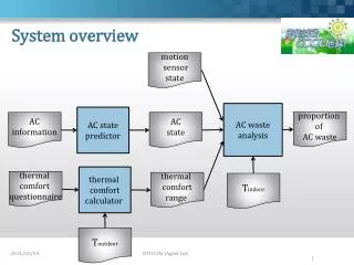
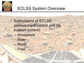
ECLSS System Overview. Subsystems of ECLSS (environment control and life support system) Atmosphere Water Waste Food. Overview of ECLSS subsystems. FOOD. WASTE. WATER. AIR. hygiene. washer. Food System. Water System. Ultra Filtration. Hygiene Water. RO. AES. Brine Water. Food

ECLSS System Overview
E N D
Presentation Transcript
ECLSS System Overview • Subsystems of ECLSS (environment control and life support system) • Atmosphere • Water • Waste • Food
Overview of ECLSS subsystems FOOD WASTE WATER AIR
hygiene washer Food System Water System Ultra Filtration Hygiene Water RO AES Brine Water Food Preparation Iodine Removal Bed VCD Monitoring Milli Q Pretreated Urine Food Trash ISE Monitoring MCV Iodine Plant Hab Pretreatment Oxone, Sulfuricacid Potable Water Atmosphere System Waste System Fecal Urine TCCA SPWE Vent to Mars Atm. H2 Compactor Atmospheric Condenser Solid Waste Storage EDC Compactor CO2 ECLSS System O
Human Consumables • Atmosphere • O2 consumption: 0.85 kg/man-day [Eckart, 1996] • CO2 production: 1.0 kg/man-day [Eckart, 1996] • Leakage (14.7psi): 0.11 kgN2/day & 0.03 kgO2/day • Water • Potable 3 L/person/day [Larson, 1997] • 1.86 Food Preparation •1.14 Drink • Hygiene 18.5 L/person/day [Larson, 1997] • 5.5 Personal Hygiene •12.5 Laundry •0.5 Toilet Flush
Human Consumables • Waste • Urine: 9.36 kg/day [Eckart, 1996] • Feces: 0.72 kg/day [Eckart, 1996] • Technology & Biomass 1.012 kg/day [Eckart, 1996] • Food • ~ 2,000 kCal per person per day [Miller, 1994]
cabin leakage N2 O2, & H2O N2 storage tanks N2 O2 crew cabin SPWE H2 & O2 TCCA T&H control H2O EDC FDS To: trash compactor To: hygiene water tank To: vent From: H2O tank To: vent H2 H2O CO2 used filters & carbon H2O Atmosphere System Schematic Specifications • Fixed mass 1,965 kg • Consumable 4 kg/day • Power 3.5 kW
Water System Schematic Specifications • Fixed mass 942.71 kg • Consumable (technologies) 0.36 kg/day • Power 2.01 kW
commode urinal fecal storage feces urine solid waste storage compactor compactor From: TCCA food trash microfiltration VCD trash To: waste water tank H2O Waste System Schematic Specifications • Fixed mass 279 kg • Consumable 2.3 kg/day • Power 0.22 kW
waste water H2O Salad Machine edible plant mass water inedible plant mass food preparation microwave food & drink food waste & packaging food storage To: trash compactor potable water H2O trash Food System Schematic Specifications • Fixed mass 1,320 kg • Consumable 4.5 kg/day • Power 3.4 kW
Habitat Layout Hatches: One at each end, one in the middle, all on bottom floor Top Floor: personal space and crew accommodations Bottom Floor: Lab, equipment, and airlocks Basement: Storage, equipment, supports and wheels
Leakage • ISS Leakage – 1.24 kg/yr/m3 • Lunar Base Concept – 1.83 kg/yr/m3 • MOB Habitat – 530 m3 • Estimated Habitat Leakage – 657-791 kg/yr • Assume similar: • Differential pressure • Materials • Thickness of outer shell
Future Tasks • Load analysis • Insulation • Shielding • Layout – more detail • Volume Allocation – more detail
Requirement Must reject 25 KW (from Power system) Must cool each subsystem Must use a non-toxic interior fluid loop External fluid loop must not freeze Accommodating transit to Mars Design Rejects up to 40 KW via radiator panels Cold plates for heat collection from each subsystem Internal water fluid loop External TBD fluid loop During transit heat exchangers will connect to the transfer vehicle’s thermal system Thermal System Overview
Current Status • Radiator panels sized for HOT - HOT scenario • Fluid pumps sized • Initial power usage estimated • Initial plumbing estimates • Initial total mass estimates • System schematics
Thermal Components *Power is for two pumps in operation at one time, not six
Future Tasks • Cold plates and sizing TBD • External fluid loop TBD • Heat exchangers TBD • Radiator locations TBD • Fluid storage TBD • COLD - COLD scenario TBD • Sensors/Data/Command structure TBD • FMEA • Report
C3 Design Status • Qualitatively defined data flows • Created preliminary design based on data flows, mission requirements and existing systems • Command and Control System • Sizing and architecture based on ISS • Mass, power and volume breakdowns • Communications System • Sizing and architecture based on existing systems • Mass and power breakdowns • Assuming at least 1 Mars orbiting communications satellite
ISRU Plant Nuclear Reactor Crew Mars Env’mt Earth C3 I/O Diagram Robotics & Automation Structure EVAS Mars Com Sat CCC Crew Accommodations ECLSS Legend Power ENERGY Packetized Data Telemetry/Data Command/Data Voice Video Electrical power Heat Thermal ISRU
Command and Control System Comm System Tier 1 Command Computers (3) RF Hubs (3) User Terminals (6) Tier 1 Emergency Computer (1) Tier 2 Subsystem Computers (4) Tier 2 Science Computers (2) File Server (1) Tier 3 Subsystem Computers (8) Caution & Warning (?) C3 System Sensors Firmwire Controllers Experiments Other Systems Control System Diagram V 1.0, 11/8/2003 Legend Ethernet RF Connection Mil-Std 1553B Bus TBD
Communications System • High gain system • Link with Earth and long range rovers • Normally communicates through orbiting satellite • Emergency option for direct Earth communications • Medium gain system • Emergency to satellite if high gain system fails • UHF system • Local communications with EVA crew
C3 Future Tasks • Quantify data flows and adjust preliminary design • Determine spare parts needs • Estimate cabling mass • Address total system mass overrun • Define maintenance and operational requirements • FMEA • Report
Mission Operations • Past • Derived Requirements • From DRM • Reviewed Literature • Larson and Pranke • MSIS
Mission Operations • Past • Created Functional Diagram (Crew Accommodations) • Diagram goes here
Mission Operations • Present • Creating lists of operations required for each subsystem • Crew Operations • example • Automated Operations • example
Mission Operations • Present • Giving input to subsystems • Based on human factors considerations • Incorporating MSIS, Larson and Pranke, experience • Determining mass, power, volume requirements for crew accommodations
Mission Operations • Future Plans • Continue integration of human factors into subsystems • Create tentative crew schedules • Equipment Maintenance • Housekeeping • Scientific Tasks • Paperwork • Personal Time
Robotics and Automation • Number/Functions of rovers • Three classes of rovers • Small rover for scientific exploration • Medium rover for local transportation • Large pressurized rover for long exploration and infrastructure inspection • Power/Mass specs on all rovers • Power specs on robotic arms
Automation items (in progress) • Automated doors in case of depressurization • Deployment of habitat • Connection to power plant • Inspection of infrastructure • Site preparation • Communications hardware • External monitoring equipment • Deploy radiator panels • Deployment/Movement of scientific equipment
External Vehicular Activity Systems • EVA tasks will consist of constructing and maintaining habitat, and scientific investigation • EVAS broken up into 3 systems • EVA suit • Airlock • Pressurized/unpressurized rovers
EVAS – EVA Suit • Critical functional elements: pressure shell, atmospheric and thermal control, communications, monitor and display, nourishment, and hygiene • Current suit is much too heavy and cumbersome to explore the Martian environment • ILC Dover is currently developing the I-Suit which is lighter, packable into a smaller volume, and has better mobility and dexterity
EVAS – EVA Suit • I-Suit specs: • Soft upper-torso • 3.7 lbs/in2 (suit pressure can be varied) • Easier to tailor to each individual astronaut • ~65 lbs • Bearings at important rotational points • Greater visibility • Boots with tread for walking on Martian terrain • Parts are easily interchangeable (decrease number of spare parts needed)
EVAS - Airlock • Independent element capable of being ‘plugged’ or relocated as mission requires • Airlock sized for three crew members with facilities for EVA suit maintenance and consumables servicing • There will be two airlocks each containing three EVA suits • Airlock will be a solid shell (opposed to inflatable) • The airlock will interface with the habitat through both an umbilical system and the hatch
EVA – Pressurized Rover • Nominal crew of 2 – can carry 4 in emergency situations • Rover airlock capable of surface access and direct connection to habitat • Per day, rover can support 16 person hours of EVA • Work station – can operate 2 mechanical arms from shirt sleeve environment • Facilities for recharging portable LSS and minor repairs to EVA suit • The rover will interface with the habitat through both an umbilical system and the hatch
EVAS – Umbilical System • Connections from the habitat to the airlock and rover will be identical • Inputs from habitat to airlock/rover (through umbilical system) • Water (potable and non-potable) • Oxygen/Nitrogen • Data • Power • Outputs from airlock/rover to habitat (through umbilical system) • Waste water • Air • Data
External Vehicular Activity Systems • EVAS is primarily responsible for providing the ability for individual crew members to move around and conduct useful tasks outside the pressurized habitat • EVA tasks will consist of constructing and maintaining habitat, and scientific investigation • EVAS broken up into 3 systems • EVA suit • Airlock • Pressurized Rover
EVAS – EVA Suit • Critical functional elements: pressure shell, atmospheric and thermal control, communications, monitor and display, nourishment, and hygiene • Current suit is much too heavy and cumbersome to explore the Martian environment • ILC Dover is currently developing the I-Suit which is lighter, packable into a smaller volume, and has better mobility and dexterity
EVAS – EVA Suit • I-Suit specs: • Soft upper-torso • 3.7 lbs/in2 (suit pressure can be varied) • Easier to tailor to each individual astronaut • ~65 lbs • Bearings at important rotational points • Greater visibility • Boots with tread for walking on Martian terrain • Parts are easily interchangeable (decrease number of spare parts needed)
EVAS - Airlock • Independent element capable of being ‘plugged’ or relocated as mission requires • Airlock sized for two crew members with facilities for EVA suit maintenance and consumables servicing • There will be two airlocks each containing two EVA suits • Airlock will be a solid shell (opposed to inflatable) • The airlock will interface with the habitat through both an umbilical system and the hatch
EVA – Pressurized Rover • Nominal crew of 2 – can carry 4 in emergency situations • Rover airlock capable of surface access and direct connection to habitat • Per day, rover can support 16 person hours of EVA • Work station – can operate 2 mechanical arms from shirt sleeve environment • Facilities for recharging portable LSS and minor repairs to EVA suit • The rover will interface with the habitat through both an umbilical system and the hatch
EVAS – Umbilical System • Connections from the habitat to the airlock and rover will be identical • Inputs from habitat to airlock/rover (through umbilical system) • Water (potable and non-potable) • Oxygen/Nitrogen • Data • Power • Outputs from airlock/rover to habitat (through umbilical system) • Waste water • Air • Data
Current Status • Mars Environment Information Sheet has been created • The information has been distributed to all subsystems and located on MOB website • ISRU plant options have been summarized • Initial plumbing designs and estimates • Initial total mass estimates • System schematics
Zirconia Electrolysis • Advantages • Simple operation • Produces Oxygen CO + CO2 Zirconia-walled Reactor 1000 °C CO2 O2 Heat Requires 1562 W-day/kg of Oxygen ISRU Plant Summary