Download
1 / 21
280 likes | 548 Views
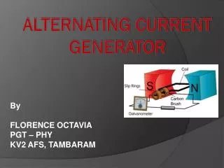
Chp . 22 Induction & Alternating Current. Electromagnetic Induction. Induced current is produced in a conducting coil when it is exposed to a changing magnetic field This is the mechanism behind generators making electricity. Induced EMF.

E N D
Electromagnetic Induction • Induced current is produced in a conducting coil when it is exposed to a changing magnetic field • This is the mechanism behind generators making electricity.
Induced EMF • This is the electromotive force (emf) produced across a conductor due to its motion through a magnetic field. • Formulas: emf= vBL (velocity x length of the conductor times the magnetic field strength) Faraday’s Law of emf in coils : emf= -N( AB cosθ) t where N is the number of coils of wire on the rotating body.
Induced EMF continued • Then if the 0.22 amps and 0.11V from the previous problem were fed into a 25 light bulb; How much power would be delivered? How much energy? • I=ΔV/R so 0.11V/25.5 = 4.3 mA • P = IΔV = (0.0043A)(0.11V)= 0.4 mW. • And power is energy / time: E = Pt ; so (0.4 mW )(6O s) = 0.028 Joules (not too bright)
Magnetic Field of a Solenoid • A solenoid is a long wire wound in the form of a helix. • Tightly wound solenoids produce a very strong magnetic field inside of the loops. The strength depends on the number of loops of wire. • Solenoids are used widely in switches.
Differences in Electric and Magnetic Fields A. The electric force is always in the direction of the electric fieldwhereas the magnetic force is perpendicular to the magnetic field. B. The electric force acts on a charged particle independent of the particle's velocity. The magnet force acts on a charged particle only when the particle is in motion.
Induced Electrical Current • Just like moving charges produce a magnetic field…. a moving magnetic field can produce an Induced Electrical Current. • Faraday’s Law of induction: relates magnetic flux change to the electromotive force (emf) or potential electrical change (voltage).
Faraday’s Law of Electromagnetic Induction: • The average emf (E ) of a coil with N loops is : E = -N (/t) where is the change in magnetic flux through one loop over the time interval it occurs. This is a rate of change of flux over time (calculus). is equal to BA cos θ The Unit for EMF or E is the Volt.
Faraday Example: Emf in a Rotating Coil: • A flat coil of wire with area of 0.02m2 with 50 turns is started at θ = 0o to a constant magnetic field of 0.18T and is rotated through 30o in 10 seconds. • What is the emf? E = -N (/t) = -N(BA cosθ/ t) = -NBA (cosθ/ t ) = -(50turns)(0.18T)(0.02m2)(cos 30 –0)/10s = +0.24 Volts
Lenz’s Law-- Easy Version • Universal Law of Change: NO ONE LIKES IT !! Even Circuits ! • Lenz’s law says that induced current in a loop will resist any change in the current due to a change in the magnetic flux around a circuit • When you move a magnet the induced current will flow in the direction as to oppose the change that produces it.
Lenz’s Law • Lenz’s Law states that the induced current will be in a direction to oppose the change in magnetic flux that produced the current. • This is the polarity of the induced emf. The induced emf always has a polarity which would produce a current whose magnetic field would oppose the change in flux that caused the induced emf in the first place.
Maximum emf for a Generator Emf = NAB ω N = number of loops A = cross sectional area B= magnetic field strength ω = angular frequency of rotation (2πf) *Example 22B page 805
Root Mean Square Current : Irms rms current is the same as the amount of direct current that would dissipate the same energy in a resistor as is dissipated by the instantaneous alternating current over a complete cycle. Irms = ΔVrms R Page. 808 P = (Irms)2 R = ½ (Imax )2 R Irms = Imax = .707 Imax √2 ΔVrms = ΔVmax = .707 ΔVmax √2 *Table 22-2
Transformer Equation Page. 815 ΔV2 N1 = N2 ΔV1 ΔV2 = N2 ΔV1 N1 ΔV1 I1 = ΔV2 I2 N= # of turns V = Voltage…potential difference Examples 22 C and 22 D pg 809 and 817
HmwkChp. 22 Book #2 • 22A pg. 800 1,2 ( I = 14A) • 22B pg. 806 1,3 • 22C pg. 810 1,3,5 • 22D pg. 818 1,3,5
HmwkChp. 22 WKBK #3 • 22A 2. t= 135sec 3. t = 6.3 x 10 -5 sec 4. emf = -320 V 6. A = 4 m2 • 22B 2. N= 20 turns ** EXAMPLE 3. B = 4.1 x 10 -4 T 5. ω = 1600 rad/sec 6. ω = 3780 rad/sec • 22C 1. A. Irms = 2000A B. I max = 2800 A C. P= 2.4 x 10⁵ W 3. I max = 3500A R = 22Ω 6. ΔV= 25kV • 22D 2. ΔV1 =120V 4. N= 2000 turns 3. ΔV2 =.18 V ΔV1 =.0022 V 7. I 1 = 55 A N= 360 turns