Understanding Data Link Layer Functions: Flow Control and Error Management
The Data Link Layer plays a crucial role in data communication by ensuring reliable transfer of information across the physical link. This chapter explores the various functions of the Data Link Layer, including frame synchronization, addressing, error control, and flow control. We discuss methods such as Stop-and-Wait and Sliding-Window flow control, and error detection mechanisms like parity checks and CRC. Additionally, we highlight the importance of efficient data transmission and the challenges associated with error correction and management in modern networks.


Understanding Data Link Layer Functions: Flow Control and Error Management
E N D
Presentation Transcript
Chapter 7Data Link Control Read Chapter 7 & pay attention to the reasons why the Data Link Layer exists (regulates data rate among other functions).
Source node Destination node Application Application Presentation Presentation Session Session Intermediate node transport transport Packets Network Network Network Frames Data link Data link Data link Bits Physical Physical Physical Signals Physical Layer
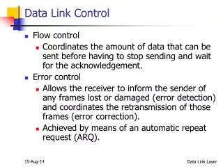
Data Link Layer • Provides for reliable transfer of information across physical link • Includes: • transmission of blocks of data (“frames”) • synchronization • error control • flow control
Data Link Layer Functions • Frame Synchronization - Create abstraction of “frame-at-a-time” channel for higher layer (start & end of each frame must be recognizable) • Addressing - Needed when many nodes share transmission link • Flow Control - Control rate of transmission to prevent overflow of receiver's buffers • Error Control - Correct transmission errors (by retransmission) or by error correction schemes • Sequence Control - Receiver must be able to distinguish control information from data • Link Management - Initiation, maintenance, & termination of connections
Flow Control • Necessary when data is being sent faster than it can be processed by receiver • Computer to printer is typical setting • Can also be from computer to computer, when a processing program is limited in capacity
Stop-and-Wait Flow Control • Simplest form of Flow Control • Source may not send new frame until receiver acknowledges the frame already sent • Very inefficient, especially when a single message is broken into separate frames
Sliding-Window Flow Control • Allows multiple frames to be in transit • Receiver sends acknowledgement with sequence number of anticipated frame • Sender maintains list of sequence numbers it can send, receiver maintains list of sequence numbers it can receive • ACK (acknowledgement) supplemented with RNR (receiver not ready)
Error Control Process • All transmission media have potential for introduction of errors • Error control process has two components • Error detection • Error correction
Error Detection • Parity Check • Cyclic Redundancy Check (CRC)
Error Correction • Two types of errors • Lost frame • Damaged frame • Automatic Repeat reQuest (ARQ) • Error detection • Positive acknowledgment • Retransmission after time-out • Negative acknowledgment and retransmission
Stop-and-Wait ARQ • One frame received and handled at a time • If frame is damaged, receiver discards it and sends no acknowledgment • Sender uses timer to determine whether or not to retransmit • Sender must keep a copy of transmitted frame until acknowledgment is received • If acknowledgment is damaged, sender will know it because of numbering
Go-Back-N ARQ • Uses sliding-window flow control • When receiver detects error, it sends negative acknowledgment (REJ) • Sender must begin transmitting again from rejected frame • Transmitter must keep a copy of all transmitted frames
Flow Control • Technique for controlling data rate so that sender does not over-run receiver • Two approaches exist: • 1. Stop-and-wait • 2. Sliding-window
Stop & Wait Flow Control • 1. Sender sends a frame • 2. Receiver receives frame & acknowledges it • 3. Sender waits to receive “ack” before sending next frame (If receiver is not ready to receive another frame it holds back the ack) • * One frame at a time is sent over the transmission line
Utilization (Efficiency) of Stop & Wait • Propagation time: time taken for signal to travel from S to R. Thus first bit transmitted at t=0 arrives at R at t = T p = d / V.
Utilization (Efficiency) of Stop & Wait • Transmission time: time taken to emit all bits of frame at sender = T t = L / B. In figure 7.2 Page 197, Transmission Time=1, therefore a = Propagation (Delay) Time
Utilization (Efficiency) = U Note: a=Tp/Tt or Tp=aTt Vertical-Time Sequence Diagram
The effect of a on utilization This shows that for large a (Propagation Time>Transmission Time), the line is under-utilized
Utilization (Efficiency) of Stop & Wait • With stop & wait scheme, for high channel utilization, we need a low a (since U= 1/(1+2a)) • However, in practice it is desirable to limit frame length L because • error probability increases with L • high average delay with multi-point lines • buffer size limitations • So a more efficient scheme is called for, especially with WAN/satellite communication
Utilization (Efficiency) of Stop & Wait Examples • 1). WAN using ATM • L = 53 bytes = 424 bits, B= 155.52 Mbps, d=1000km Þ T t = 424 / (155.52 x 10⁶ ) = 2.7 x 10⁻⁶ seconds assuming optical fiber, T p = 10 6 m / (3 x 10⁸ m/sec) = 0.33 x 10⁻² seconds Þ a = (0.33 x 10⁻² )/(2.7 x 10-6 ) = 1200 Þ U = 1/2401 = 0.0004 • 2). LAN • d = 0.1 ~ 10 km, B = 10 Mbps, V = 2 x 10⁸ m/sec • L = 1000 bits Þ a = 0.005 ~ 0.5 Þ U = 0.5 ~ 0.99 • 3). Digital trans. vis modem over voice-grade line • B = 28.8 kbps, L = 1000 bits, d = 1000 m Þ a = (28.8 kbps * 1000 m) / (2 x 10⁸ m/sec x 1000 bits) = 1.44 x 10⁻⁴Þ U = 1.0, if d = 5000 km, a = (28.8kbps x 5000km) / (2 x 108 x 1000bits) = 0.72 Þ U = 0.4
Sliding-Window Flow Control • Pipeline transmission of successive frames • Transmit up to “N” frames if necessary without receiving acks. • Wait for acks when “N” unacked frames in transit • For full duplex transmission each station needs a sending window & receiving window.
Utilization: U is a function of a and N • Case 1: N > 1 + 2a : U = 1 • Ack for frame 1 reaches Sender before transmission of Nth frame Þ continuous transmission possible
Utilization: U is a function of a and N • Case 2: N < 1 + 2a : U = N / (1 + 2a) • Wasted time between N and 1 + 2a
Error Detection • Basic Principle • Transmitter: For a given bit stream M, additional bits (called error-detecting code) are calculated as a function of M and appended to the end of M • Receiver: For each incoming frame, performs the same calculation and compares the two results. A detected error occurs if there is a mismatch
Error Detection • Two common techniques • Parity checks • Cyclic redundancy checks (CRC) • Parity Check • One extra “parity” bit is added to each word • Odd parity: bit added so as to make # of 1’s odd • Even parity: makes total # of 1’s even • Single parity is very effective with white noise (noise on a line without any active signals on it; e.g., Thermal Noise, see chapter 3), but not very robust with noise bursts (which may extend over whole word duration.)
Cyclic Redundancy Checks • Powerful error detection method, easily implemented • Message (M) to be transmitted is appended with extra frame checksum bits (F), so that bit pattern transmitted (T) is perfectly divisible by a special “generator” pattern (P) - (divisor) • At destination, divide received message by the same P. If remainder is nonzero Þ error
Cyclic Redundancy Checks • Let • T = (k+n)-bit frame to be transmitted, n<k • M = k-bit message, the first k bits of T • F = n-bit FCS, the last n bits of T • P = n+1 bits, generator pattern (predetermined divisor) • The concept uses modulo-2 arithmetic • no carries/borrows; add º subtract º XOR
Cyclic Redundancy Checks • Method • Extend M with n ‘0’s to the right (º 2 n M)(shift left by n bits • Divide extended message by P to get R (2 n M / P = Q + R/P) • Add R to extended message to form T (T = 2 n M + R) • Transmit T • At receiver, divide T by P. Nonzero remainder means: Þ error Note: Remainder R=F=FCS in these examples Note: R+R=0 in mod-2 arithmetic
Cyclic Redundancy Checks Examples • M = 110011, P = 11001, R = 4 bits • 1. Append 4 zeros to M, we get 1100110000 -For each stage of division, if the number of dividend bits equals number of divisor P bits, then Q=1, otherwise Q=0 -Also, see example on page 204
Cyclic Redundancy Checks • Exercise: Compute the frame to be transmitted for message 1101011011 using P = 10011 • Answer: 11010110111110
Cyclic Redundancy Checks • Can view CRC generation in terms of polynomial arithmetic • Any bit pattern º polynomial in dummy variable X as shown in the following example: • e.g., M = 110011 º 1·X5 +1·X4 +0·X3 +0·X2 +1·X+1·X0 \ M(X) = X5 +X4 +X+1
Cyclic Redundancy Checks • CRC generation in terms of polynomial • Append n ‘0’s º Xn M(X) • Modulo 2 division ® • Transmit Xn M(X)+R(X) = T(X) • At receiver:
Cyclic Redundancy Checks • Commonly used polynomials, P(X) • CRC-16 = X16 +X15 + X2 +1 • CRC-CCITT = X16 +X12 + X5 +1 • CRC-32 = X32 +X26 + X23 + X22 +X16 + X12 + X11 +X10 +X8 + X7 +X12 + X4 + X2 +X+1
Can detect • 1. All single-bit errors • 2. All double-bit errors, as long as P(X) has a factor with at least three terms (as long as p has at least three 1s) • 3. Any odd number of errors, as long as P(X) contains a factor (X+1) • 4. Any burst error for which the length of the burst is less than the length of the FCS • 5. Most larger burst errors
Why? T=Transmitted frame E=Error pattern with 1s in positions where errors happen Tr=Received frame • Error can also be represented by polynomial, E(X). • Tr(X) = T(X) E(X) • Error is undetectable if E(X) is divisible by P(X) • P always has at least two terms, Xn , 1 (most & least significant bits equal to 1) • 1. Single-bit error: E(X) = Xi (one bit=1) • P(X) = X n + … +1 \ Error is detectable since E(X) is not divisible by P(X)
Why? • 2. Double-bit error: E(X) = Xi +Xj = Xi (1+Xk ), k=j-i>0 • P(X) does not divide into Xi • P(X) can be chosen which does not divide 1+Xk up to the maximum value of k (i.e., up to the practical frame length). (e.g., X15 + X14 +1 will not divide 1+Xk for any k below 32768)
Why? • 3. No polynomial with an odd # of terms is divisible by (X+1) • Assume E(X) has an odd # of terms and is divisible by (X+1). Then E(X) = (X+1)Q(X). E(1) = (1+1)Q(1) = 0. However, E(1) cannot be zero since it has an odd # of 1’s • 4. A burst error of length r < n can be represented by Xi (Xr-1 + ··· +1). • P(X) does not divide into Xi • P(X) which is a polynomial of degree n cannot divide into Xr-1 + ··· +1 since r-1<n.
Implementation • Implemented by a circuit consisting of exclusive-or gates and a shift register • The shift register contains n bits (length of FCS) • There are up to n exclusive-or gates • The presence or absence of a gate corresponds to the presence or absence of a term in P(X)
Example Note:R=01110 see pages 206-207 Shift Register Circuit for dividing by the polynomial X5 +X4 + X2 +1
Error Control See page 208
Error control techniques • Forward error control: • Error recovery by correction at the receiver [Forward Error Correction (FEC)] • Backward error control: • Error recovery by retransmission [Automatic Repeat Request (ARQ)]
ARQ • Based on • Error detection • Positive ack • Retransmission after timeout • Negative ack. And retransmission • ARQ • Stop-and-wait ARQ • Continuous ARQ • Go-back-N ARQ • Selective-reject ARQ
Stop & Wait ARQ • Simple and minimum buffer requirement, but inefficient • Sender transmits message frame • Receiver checks received frame for errors; sends ACK/NAK • Sender waits for ACK/NAK. NAK Þ retrans; ACK Þ next frame
Stop & Wait ARQ • Frame/ACK could be lost Þ Uses a timeout mechanism • Possibility of duplication Þ Number frames • Only need a 1-bit frame number alternating 1 and 0 since they are sent one at a time
Go-back-N ARQ • If the receiver detects an error on a frame, it sends a NAK for that frame. The receiver will discard all future frames until the frame in error is correctly received. Thus the sender, when it receives a NAK or timeout, must retransmit the frame in error plus all succeeding frames. (Sender must maintain a copy of each unacknowledged frame.)
Selective-reject ARQ • The only frames retransmitted are those that receive a NAK or which timeout • Can save retransmissions, but requires more buffer space and complicated logic • See Figure 7.9b Page 212
Maximum window size (with n-bit sequence number) • Go-back-N : 2n - 1 • Selective-reject : 2n-1