SNS Reliability Program
This document outlines the operational goals, RAMI modeling, and management information systems utilized within the Spallation Neutron Source (SNS) at the Oak Ridge National Laboratory. It emphasizes the importance of predictive maintenance strategies based on performance data, configuration management, and effective metrics for tracking reliability and availability. By implementing robust data systems, the SNS aims to minimize unscheduled downtime and optimize maintenance practices for continuous improvement in facility operations.

SNS Reliability Program
E N D
Presentation Transcript
SNS Reliability Program George Dodson Research Accelerator Division Spallation Neutron Source
Topics • Goals • RAMI Modeling • Management Information Systems • Metrics • Maintenance Management • Configuration Control
Current 1ms SNS Accelerator Complex Front-End: Produce a 1-msec long, chopped, H- beam LINAC: Accelerates the beam to 1 GeV Accumulator Ring: Compress 1 msec long pulse to 700 nsec H- stripped to protons Deliver beam to Target 186 MeV 2.5 MeV 1000 MeV 87 MeV 387 MeV Ion Source CCL SRF, b=0.61 RFQ SRF, b=0.81 DTL Chopper system makes gaps 945 ns mini-pulse Current 1 ms macropulse Monthly Metrics for August, 2006
ModelingPredict the Performance Data • Modeling sets Your Expectations for Reliability/Availability: • Static Model • Markov Chain Model • R(t) is Constant • MTBF/MTTR inputs from Vendor Information and Industrial Standards • Monte Carlo Model • R(t) is an input function. You get to pick where you are on the function. • Use Actual Performance Data to Validate the Model
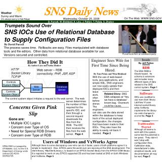
Management Information Systems (Oracle) Acquire the Data • Beam Time Accounting • Operations Accounting System (OAS) • Shift by Shift account of downtime • Electronic Logbook • Narrative account of shift activities including threaded discussion of breakdown and repair • CMMS – DataStream 7i (Infor) • Equipment Tracking • Asset Structure tables with parent-child relationships • “Cradle to Grave” tracking by position, location, asset • Asset status (Installed, In-Repair, Spare, Disposed Of) • Work Control • Use the same “Data Structures” for each: System, Sub-System, Sub-Sub-System , Sub-Sub-Sub-System, Asset, Position. Location • All 3 MIS Systems “Tied Together” through the Work Order Numbers
Data Management Analyze and Use the Data • Robust data system for tracking and trending, including MTTF, MTTR, Spares Inventory, Fault Tracking, etc. • Comparison of MTBF/MTTR data with the Reliability Model and industrial standards with an eye to the root cause of failures with higher than expected failure rates. • Go after the highest sources of downtime • Effectively utilize Control System Monitoring Data – filtering and pattern analysis to Detect the Onset of Pre-Failure Behavior so that you can replace the component in a Maintenance Period
Operations Report forDecember 20-26, 2010(Run FY11-1) Research Accelerator Division Spallation Neutron Source
Presentation_name Operating Statistics – December 20-26, 2010
Unscheduled downtime ≥ 0.1 hr. for the last week Unscheduled downtime by number of occurrences >1 (beam and non-beam downtime combined)
Maintenance Management • Predictive/Preventive maintenance schedules based on accepted practices for standard equipment and experience/MTTF data for specialized equipment • Manufacturer data is NOT always the best • EPRI Database • Proactive replacement of equipment showing pre-failure behavior • Effective use of scheduled and discretionary weekly maintenance opportunities • Avoid “run to failure” – “replace/repair when possible” • Spares inventory • Proactive replacement of equipment at a pre-determined % of measured lifetime – mature facilities with lots of data
Configuration Control One of the worst things that you can do at a mature, operating facility is allow changes to the design basis that, though the Law of Unintended Consequences, causes a failure that prevents the facility from operating. • Corollary – Smart People Sometimes Do Dumb Things.
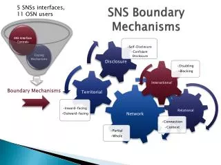
Configuration Control Policy • Configuration management (CM) is defined as a process for establishing and maintaining consistency of a configuration item’s performance, functional and physical attributes, and its documented configuration with its requirements, design and operation information throughout its lifetime. • Configuration management control begins with baselining of requirements, the Design Criteria Document (DCD and DCN) process, and ends with decommissioning of equipment in the operational SNS. • Responsibility for Configuration Control of Systems, Structures, Components andSoftware (SSCS)resides with the System Engineer.
Configuration Control Objectives • To document and provide full evidence of an SSCS’s previous history (when available) and present configuration including the status of compliance of an item to its physical and functional requirements. • To ensure that staff who operate, use, repair or maintain an SSCS or who have the potential to affect its configuration use correct, accurate, and current documentation. • To ensure that new designs and changes to existing designs for systems, structures, components and software utilize best engineering practice, follow from an approved set of specifications, and are appropriately documented. • To ensure that the deployment of a new SSCS or a change to an existing SSCS is authorized. • To ensure that the impact on performance due to the deployment of a new SSCS or a change to an existing SSCS is fully understood, and that the risks associated with the deployment are considered.
Configuration Management Policy • SNS-OPM 9.A-1 SNS Configuration Management Policy • Configuration Identification • Configuration Change Management • Configuration Status Accounting • Configuration Verification and Audit • Commercial Off-The-Shelf, Non-Developmental Items, and Commercially Available Software • Proceduresfor Design Development and Design Change • SNS-OPM 9.A-2 SNS Design Development Procedure • SNS-OPM 9.A-3 SNS Design Change Procedure
Since 2006 operational performance improvement at SNS has been dramatic
Initial and ongoing operation revealed system weakness that have been substantially addressed
SNS Management in FY10 decided to emphasize availability improvement while holding proton beam power at or near 1MW • Resources were allocated to address major contributors to down time, particularly the HVCM • Replacement of some highly stressed oil filled capacitors with less lossy solid units that led to fewer and lower consequence capacitor failures and easier fault recovery. • IGBT drive gate synchronization turn off that reduced IGBT failures by more than a factor of 10. • The single largest downtime contributor to RF systems, the MEBT RF Power Amplifiers, were replaced with new solid state devices. • The 2MHz RF amplifier that drives the ion source plasma was removed from the 65KV floating deck to ground potential and is now powered through an isolation transformer, an improvement that allows for better diagnosis of failures and quicker repair.
Recent targeted actions based on detailed system engineering analysis have substantially reduced HVCM failure contributions to down time Performance improvement from system modifications installed during 2010 Winter and Summer outages – For the FY 2011-1 run period HVCM downtime accounted for only 1.36% of the scheduled beam time compared to 5.7% for all of FY 2010
Analysis of FY10 and FY11 availability data indicate that a new approach to performance improvement is needed • Events of duration 1 minute to 1 hour contribute to about 4% down time • Events of duration >3 hours drive the overall structure and contribute the majority of recent cumulative down time • These longer events have the greatest impact on experiment outcomes
Summary • The SNS has an evolving Reliability Program • We are making good progress • We realize that we are “young” and that we have not reached Terminal Mortality for many systems. • The final goal is 95% availability. • A Plan has been developed. • It may be too costly to be implemented. Why? • Going from 90% to 95% is only another 5.5% in beam delivery, but it is a factor of 2 in downtime reduction. Diminishing returns! The facility Science impact will likely be larger from another beamline instrument (Spectrometer). • We will likely make more modest evolutionary (not revolutionary) changes to our operating base.
Analysis • Of operating trends to act on leading indicators of failure in a predictable way • Of equipment failures to understand root causes (design, installation, fabrication, etc.) and to fold into computation of spare inventories or anticipate obsolescence issues • Of vulnerabilities (single-point failure modes) • Of day-to-day internal, less frequent formal internal and external assessments and off-normal events. • Of fault correction data to determine needed changes to the response model (on-call, recovery algorithms, etc.) • 00.00 hours - Diagnosis • 00.00 hours - Transit • 00.00 hours - Repair Time • 00.00 hours - Recovery Time