Download
1 / 76
760 likes | 873 Views
This paper by Vadim Dudnikov of Muons, Inc. discusses advancements in the development of highly polarized ion sources, emphasizing the architecture of a Universal Atomic Beam Polarized (ABP) ion source. Key innovations include the suppression of unpolarized H-/D- ions by employing new designs for dissociators, plasma generators, and ionizers. The study highlights the importance of high beam polarization for collider productivity and outlines system designs aimed at producing intense polarized ion beams, including polarized 3He- ions, significant for future collider applications.

E N D
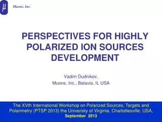
m Muons, Inc. PERSPECTIVES FOR HIGHLY POLARIZED ION SOURCES DEVELOPMENT Vadim Dudnikov, Muons, Inc., Batavia, IL USA The XVth International Workshop on Polarized Sources, Targets and Polarimetry (PTSP 2013) the University of Virginia, Charlottesville, USA, September 2013
OUTLINE Features of an Universal ABP ion source are discussed. The main innovation of this approach is the strong suppression of parasitic generation of unpolarized H-/D- ions by using novel designs of the dissociator, plasma generator, and surface-plasma ionizer, extraction system, which prevent adsorption and depolarization of particles from the polarized atomic beam. The same system with some modifications can be capable of producing positive and negative ion beams of different species including polarized and unpolarized H-, D-, H+, D+, 3He, and Li. Production of polarized 3He- ion beam with intensity ~ mA will be discussed
INTRODUCTION *High beam polarization degree is essential to the scientific productivity of a collider. *A figure-8 shape of booster and collider rings is an optimized solution to preserve ion beam polarization by avoiding spin resonances during acceleration and to ensure energy independence of spin tune. *In addition, a figure-8 shape ring is the only practical way for accelerating and storing polarized deuterons at a medium energy range. If there is no depolarization during acceleration and storage, the final beam polarization is determined by the initial polarization at extraction from the ion source. * Ion sources with performances exceeding those achieved today is a key requirement for the development of the next generation high-luminosity high-polarization colliders.
Budker Institute of Nuclear Physicswww.inp.nsk.su Novosibirsk State University www.nsu.ru Many components developed in BINP+NSU are used in advanced versions of PIS
Requirements to the polarized source. • Requirement of ion sources intensity was decreased for many orders by development of charge exchange injection, capable to accumulate beams during tens thousand turns. • High intensity ~ 5·1011 H-/pulse at 200 MeV after the Linac. At booster beam intensity acceptances are limited by about 1·1011 protons/bunch. The intensity excess can be used to reduce transversal and longitudinal beam emittances by a strong dynamical collimation in the Booster. • Highest possible polarization is required to reduce a systematical and statistical errors in polarization experiments. Double spin asymmetry statistical error is proportional to ~ 1/sqrt(L P4), therefore a 5% polarization increase in the source (or 5% polarization losses decrease in booster and EIC is effectively equivalent to 30% increase in the data taking time. • Beam intensity and polarization must be equal at spin-reversal and from pulse to pulse. ΔI/I <10-3 and ΔP/P < 1% need be reached.
Cooling Cooling to high-energy collider ring SRF linac Ion source Prebooster (accumulator ring) Medium-energy collider ring Large booster Major Components of MEIC Ion Complex The MEIC ion beam polarization design requirements are: • High polarization (over 70%) for protons or light ions (d, 3He++, and possibly 6Li+++). • Both longitudinal and transverse polarization at all IPs. • Sufficiently large lifetime to maintain high beam polarization. • Spin flipping at a high frequency. V. Morozov Report
m Muons, Inc. Existing Sources Parameters Universal Atomic Beam Polarized Sources (most promising, less expensive for repeating): • IUCF/INR CIPIOS: Pulse Width Up to 0.5 ms (Shutdown 8/02); Peak Intensity H-/D- 2.0 mA/2.2 mA; Max Pz/Pzz 85% to 95%; Emittance (90%) 1.2 π·mm·mrad. • INR Moscow: Pulse Width > 0.1 ms (Test Bed since 1984); Peak Intensity H+/H- 11 mA/4 mA; Max Pz 80%/95%; Emittance (90)% 1.0 π·mm·mrad/ 1.8 π·mm·mrad; Unpolarized H-/D- 150/60 mA • SPI Dubna up to 10 mA for D+ ( H+) [under commissioning] The D+ polarization will be up to 90% of the maximal vector (±1) &tensor (+1,-2) polarization OPPIS/BNL: H- only; Pulse Width 0.5 ms (in operation); Peak Intensity >1.6 mA; Max Pz 85% of nominal Emittance (90%) 2.0 π·mm·mrad.
Sources of Polarized Ions a review of early work First polarized-proton sources described at the INTERNATIONAL SYMPOSIUM ON POLARIZATION PHENOMENA OF NUCLEONS Basel, July 1960 The status 40 years ago: SOURCES OF POLARIZED IONS BY W. HAEBERLI ANNUAL REVIEWOF NUCLEAR SCIENCE Vol. 17, 1967 W. Haeberli, PSTP-2007, BNL, USA
BELOV Method based on 1968 proposal (NIM 62 p. 335) “ s= 22x10-16cm2 at 2keV -> 100x10-16cm2 at 10eV A.S. Belov et al. (INR-Moscow) - 20 yrs development work Intense beam of unpolarized D- from deuterium surface-plasma ionizes an atomic Beam (2x10¹⁷ H0/sec pulsed) Pulsed 4 mA H- 95% Polarization W. Haeberli, PSTP-2007, BNL, USA
DONOR: OPTICALLY PUMPED CHARGE EXCHANGE Zelenski 3 keV H+ POLARIZED H+ AND H- “SONA” TRANSITION B B L.W. Anderson (Wisconsin) - optically pumped Na as donor (1979) OPPIS: Zelenski, Mori et al. 20 years of development 1.6 mA H- 85-90% Polarization with new proton source 20-50mA possible W. Haeberli, PSTP-2007, BNL, USA
m Muons, Inc. ABPIS with Resonant Charge Exchange Ionization and Surface-Plasma D- generation • INR Moscow • H0↑+ D+ ⇒H+↑+ D0 • D0↑+ H+ ⇒D+↑+ H0 • σ~ 5 10-15cm2 • H0↑+ D−⇒H−↑+ D0 • D0↑+ H−⇒D−↑+ H0 • σ~ 10-14cm2 A. Belov, DSPIN2009
m Muons, Inc. Main Systems of INR ABPIS with Resonant Charge Exchange Ionization
Ionization of polarized atoms Resonant charge-exchange reaction is charge exchange between atom and ion of the same atom: A0 + A+ →A + + A0 •cross -section is of order of 10-14 cm2 at low collision energy •Charge-exchange between polarized atoms and ions of isotope relative the polarized atoms to reduce unpolarized background •W. Haeberli proposed in 1968 an ionizer with colliding beams of ~1-2 keV D- ions and thermal polarized hydrogen atoms: H0↑+ D−⇒H−↑+ D0
Resonance charge exchange ionizer with two steps surface plasma converter *Jet of plasma is guided by magnetic field to internal surface of cone; *fast atoms bombard a cylindrical surface of surface plasma converter initiating a secondary emission of negative ions increased by cesium adsorption. *An electron blocker collects plasma electrons, decreases electron extraction and H-destruction
INR ABPIS: Oscilloscope Track of Polarized H- ion Polarized H- ion Current 4 mA (vertical scale-1mA/div) Unpolarized D- ion current 60 mA (10mA/div) Parasitic H- current without polarized H atomic beam A. Belov
Probability of H- emission as function of work function (cesiation effect) m Muons, Inc. The surface work function decreases with deposition of particles with low ionization potential and the probability of secondary negative ion emission increases greatly from the surface bombarded by plasma particles. Dependence of work function on surface cesium concentration for W crystalline surfaces and relative yield Y of H- secondary emission for W surface index (111), right scale 18
Schematic of negative ion formation on the surface (φ>S)(formation of secondary ion emission; Michail Kishinevsky) Sov. Phys. Tech. Phys, 45 (1975)) • Affinity lever S is lowering by image forces below Fermi level during particle approaching to the surface; • Electron tunneling to the affinity level; • During particle moving out of surface electron affinity level S go up and the electron will tunneling back to the Fermi level; • Back tunneling probability w is high at slow moving (thermal) and can be low for fast moving particles; Ionization coefficient β- can be high ~0.5 for fast particles with S<~ φ
Coefficient of negative ionization as function of work function and particle speed Kishinevskiĭ M E, [Sov. Phys. Tech. Phys., 48 (1978), 773; 23 (1978), 456
Production of surfaces with low work function (cesium coverage) m Muons, Inc. The surface work function decreases with deposition of particles with low ionization potential (CS) and the probability of secondary negative ion emission increases greatly from the surface bombarded by plasma particles. The work function in the case of cesium adsorption in dependence upon the ratio of sample temperature T to cesium-tank temperature TCs for collectors of 1) a molybdenum polycrystalline with a tungsten layer on the surface, 2) (110) molybdenum, 3) a molybdenum polycrystalline, and 4) an LaB6 polycrystalline. Dependences of desorption energy H on surface Cesium concentration N for different W crystalline surfaces: 1-(001); 2-(110); 3-(111); 4-(112). 21
Probability of particles and energy reflection for low energy H particles
Influention of Cs+H co-adsorption to H-/D- reflection *Conversion Ho/H- by Scattering on W+Cs+H surface *Desorption of H- from W+Cs+H surface *Important for suppression of H-/D- production from depolarized components P. W. van Amersfoort, et al., J. Appl. Phys. 59, 241 (1986);
The low WF is need to support in dense plasma. It is necessary to inject some Cs (as shown in SNS SPS) H- beam intensity is raised after casiation but decayed exponencialli during operation
Fortunately, condition of “activation” was found in SNS SPS for efficient operation with very low Cs injection (mg/weeks, instead mg/hour) This “gift of nature” is not understudy in full scale an is not reproducible in different SPS. (Need further development)
At firs it was hypothesed, that a better cleaning of electrodes surface increases the binding energy and decrease Cs evaporation and sputtering. But it was recognized that a converter surface is deposited by dark film. Not only cleaning but deposition are important for optimal cesiation. Clean H plasma!
Distributions of elements on the converter cone surface. Sputter time in minutes. 20 min of sputtering is ~20 nanometers Carbon deposition and Cs intercolation can be important for stable SPS operation with low Cs consumption
Schematic diagram of IUCF ABPIS with resonant charge exchange ionization (was tested for long time injection of D-)
The pulsed polarized negative ion source (CIPIOS) multi-milliampere beams for injection into the Cooler Injector Synchrotron (CIS). Schematic of ion source and LEBT showing the entrance to the RFQ. The beam is extracted from the ionizer toward the ABS and is then deflected downward with a magnetic bend and towards the RFQ with an electrostatic bend. This results in a nearly vertical polarization at the RFQ entrance. Belov, Derenchuk, PAC 2001
Components of IUCF ABPIS (sextupole, ionization solenoid, RF dissociator, bending magnet, Arc discharge plasma source,
Schematic of JINR ABPIS (SPI) with resonant charge exchange ionization (polarized H+,D+)
General view of JINR ABPIS (SPI) with resonant charge exchange ionization (polarized H+,D+)
Arc discharge ion source with expansion of plasma jet (Dimov BINP 1962) Plasma density up to 10 **15 cm-3; Ionization 99.9 %, dissociation 99%, transverse ion temperature 0.005 eV; multi slit extraction (H+, He+ ~2A); H-~16 mA (H2); D-~100 mA (Na); He-~10 mA (Na). 1-gas valve; 2-triggering; 3 cathode; 4-barier washe; 5-woshed channel; 6-anode; 7-extracrion holder; 9, 10 –extraction grids.
Long pulse arc-discharge plasma generator with LaB6 cathode (heating prevents polarized particles adsorption and desorption as negative ions) Version with one LaB6 disc Version with several LaB6 discs Metal-ceramic discharge channel is developed Can be lower gas density, Higher He++ beam current
1 -current feedthrough; 2- housing; 3-clamping screw; 4-coil; 5- magnet core; 6-shield; 7-screw; 8-copper insert; 9-yoke; 10-rubber washer- returning springs; 11-ferromagnetic plate- armature; 12-viton stop; 13-viton seal; 14-sealing ring; 15-aperture; 16-base; 17-nut. Fast, compact gas valve, 0.1ms, 0.8 kHz
*Cesium oven with cesium chromate pellets (Cs2CrO4+Ti) and press-form for pellets preparation. Cesium oven with BiCs2 alloy *Cesium oven with Cs getters (Cs2ChO4 +Zr+Al+…) Fast, compact Cesium Supplies
Highly transparent fine precise extraction system A four-electrode multislit extraction consists of three multi-wire grids and a fourth cylindrical grounded electrode. The grids are made of 0.2 mm molybdenum wire. The spacing between wires is 1.0 mm. The wires are positioned on the mounting electrodes by precisely cut grooves and fastened by point welding. The mutual grid alignment accuracy is better than 0.02 mm. The gap between the first and second grids is 1.0 mm, the second and third grids—2.0 mm, the third and fourth—2.0 mm. This design increases the beam brightness relative two grids system.
BNL Polarimeter, 1.2 10**17 p/s • The H-jet polarimeter includes three major parts: polarized Atomic Beam Source (ABS), scattering chamber, and Breit-Rabi polarimeter. • The polarimeter axis is vertical and the recoil protons are detected in the horizontal plane. • The common vacuum system is assembled from nine identical vacuum chambers, which provide nine stages of differential pumping. • The system building block is a cylindrical vacuum chamber 50 cm in diameter and of 32 cm length with the four 20 cm (8.0”) ID pumping ports. • 19 TMP , 1000 l/s pumping speed for hydrogen.
Schematic of ABPIS • The PABIS includes three major parts: polarized Atomic Beam Source (ABS), ionizer, beam formation/separation,and Lemb polarimeter. • The PABIS axis is vertical and ion beam is bended to the horizontal plane. • The common vacuum system is assembled from 5 identical vacuum chambers of ABS, which provide 5 stages of differential pumping. • The system building block is a cylindrical vacuum chamber 50 cm in diameter and of 32 cm length with the four 20 cm (8.0”) ID pumping ports. • 10 TMP , 1000 l/s pumping speed for hydrogen+ 2.2 kl/s+cryopump
Further ABPIS development *Intensity and polarization of polarized beams produced by ABPIS can be improved by further optimization of ABS and ionization technique. *In particular, atomic beam formation should be studied to overcome limitations connected with a beam-skimmer interference. *Sextupole magnet system parameters should be optimized taking into account results of optimization of atomic beam formation system. *With these improvements pulsed polarized H-, (D-) ion beams with peak intensity of ~10 mA (~ 20 mA for H+ and D+ ions) and polarization of ~ 95% seems to be possible
Fine art of intense atomic beam formation (intensity limitation) INJECTION OF BACKGROUND GAS AT DIFFERENT POSITION ATTENUATION OF THE BEAM IS DEPENDENT FROM THE POSITION OF THE GAS INJECTIOJN NOT MANY EXPERIMENTAL DATA AVAILABLE D.K.Toporkov, PSTP-2007, BNL, USA
Cryogenic Atomic Beam Source BINP atomic beam source with superconductor sextupoles Two group of magnets – S1, S2(tapered magnets) and S3, S4, S5 (constant radius) driven independently, 200 and 350 A respectively; Bt~ 4.8 T. Cryostat Liquid nitrogen
Focusing magnets Permanent magnets B=1.6 T Superconducting B=4.8 T • DW = p*a2 = p*m*B/kT • B = 1.6 T DW ~ 1.5*10-2sr a ~ 0.07 rad • B = 4.8 T DW ~ 4.5*10-2 sr a ~ 0.21 rad
Polarized Gas Target, ABS and LDS Yuri Shestakov(BINP)High Density Polarized Deuterium Gas Target for the VEPP-3 Electron Storage Ring Flux of polarized deuterium atoms injected into the cell at/sec. Magnetic poletip field of superconducting magnets up to 4.8 T Pzz=0.4, target thickness viewed by the detector 8x10¹³at/cm2 13x14x400 mm Inner diam. 44 mm Dmitri Toporkov Summary of the 10th Workshop on SPIN2004 Polarized Sources and Targets PST2003
3He++ Ion source with Polarized 3He Atoms and Resonant Charge Exchange Ionization A.S. Belov, PSTP-2007, BNL, USA
Plans of ABPIS development Review of existing versions of ABPIS components for choosing an optimal combinations; General design of optimal ABPIS; Estimation availability of components and materials: Estimate of project cost and R&D schedule; Establish cooperaion: INR, A. Belov BINP, D. Toporkov, V. Davydenko, BNL, A. Zelenski, IUCF, Dubna, V. Derenchuk, V. Fimushkin, COSY/Julich, R. Gebel.
3He- sources development * For alpha particles diagnostics in fusion plasma of ITER under development He- ion source with current ~10 mA and Energy ~1 MeV (He+ current ~3 A with low emittance), Sasao et al.. * Autoionization is used for fast Heo production in ground state. Metastable He- have two lifetimes ~10 µs and ~350 µs. *We start looking for lifetime dependences of hyperfine states for possible using this dependences for polarized 3He- production. * This dependences are exist. And polarized 3He- production is possible 1s2s2p 4Po5/2 .
Polarized 3He- ions production • Fine and hyperfine structure of 3He- ions • Different hyperfine components of metastable relative autoionization 3He- negative ions with different orbital and spin projections have different lifetime relative autoionization. • Components with highest momentum 5/3 have largest lifetime ~350 μsec when components with lower momentum have lifetime ~10 μsec. 3He- ion beam composed only of hyperfine components [5/2, +-5/2> can be produced and then quenching one of the hyperfine levels by an RF resonant field can be produced 3He- beam with polarization ~100%. (S. Manson, PR A,3, 1,147,1971)
The decay curve of 4He- measured at 10 K. Temperature dependence of the measured lifetime of the 1s2s2p 4Po5/2 level of 4He-. The effect on the decay rate from photodetachment by blackbody radiation can readily be seen as a decrease in the measured lifetime above 100 K. The solid curve is a fit to the data. The insert shows a time region in which the decay of the short lived J =1/2 and J=3/2 levels dominate the intensity. (P. Reinhed, et al.,PRL 103, 213002 (2009) )
Separation of fine components of He- in the magnetic field Components with highest momentum 5/3 have largest lifetime ~350 μsec when components with lower momentum have lifetime ~10 μsec. 3He- ion beam composed only of hyperfine components [5/2, +-5/2> can be produced and then quenching one of the hyperfine component by an RF resonant field can be produced 3He- beam with ~100% polarization. The fine-structure results are: Δ53= 825.23 + 0.82 MHz, Δ51 = 8663 + 56 MHz.