
Introduction:
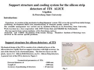
Support structure and cooling system for the silicon strip detectors of ITS ALICE S.Igolkin St.Petersburg State University. Introduction:

Introduction:
E N D
Presentation Transcript
Support structure and cooling system for the silicon strip detectors of ITSALICE S.IgolkinSt.Petersburg State University Introduction: Experience in creation of the mechanics/cooling/alignment system ITS covers the period from initial design, technology development, R&D, tests, manufacturing of elements, quality control, etc. The scientific management was carried out by Institute of Physics of St. Petersburg State University. Work was done in a close cooperation with INFN Torino Italy and NIKHEF the Netherlands. The top experts from various institutes of St. Petersburg, such as: Zentroteh and CKBM - the ministry of the Atomic Energy, Mendeleev Institute of Metrology were involved in the current specific problems. Support structure for silicon detectors of ITS Mechanical design of the ITS is consists of six cylindrical layers of the silicon detectors rigidly fixed on support structures with high accuracy. An axis of the detector is in a horizontal plane. The first two layers are the pixels, layers 3-4 – Silicon Drift Detectors, no,5-6 – Silicon Strip detectors. A general view of the ITS is shown in Figure 1 Geometrical parameters of ITS: External diameter of ~1000 mm Length of ~1400 mm Accuracy of positioning of detectors ~ 25 microns Fig. 1
Design criteria. The criteria that determine design of the support’s structure can be summarized as follows: • minimum coefficient - weight/stiffness ratio, in order to minimize the total amount of material and extending of radiation transparency of the system (<1% of X/Xo per total layer); • the mechanical support of detector is designed in a stress-free way • the required accuracy of position of the strip detector is dX ≤ 30µk • low CTE ( Coefficient of Thermal Expansion) of the various elements is used in order to avoid overstresses under temperature gradients; • Modular design; • Novel and affordable manufacturing technology; • long time reliability, more then 10 years. ALICE /ITS is composed of f 2030 silicon detectors, See Table
The choice of material for supports structures Our choice was based on knowledge and practical experience in application of high module carbon fiber, which was used for increase of rigidity of centrifuge’s rotor for isotope’s separations. Initially we applied Russian dry C.F. and domestic epoxy compound used in a serial production. Later we used ready prepregs which guaranteed stable parameters of mechanical properties in especially thin structures of detector support. The material selected that satisfies all requests is prepreg based on the High Modules Fiber type M55J. Prepreg date sheet see the Table Type M55JB EU 334 • Thickness (mm) 0.11 • Total weight (g/m2) 167 • Young module for composite (GPa) 270 • Young module for fiber (GPa) 550 • CTE of composite 1.2 x 10⁻⁶ • The ratio fiber/glue ( % ) 70/30 • Shelf life -30C° 1.5 year • Shelf life 20C° 30 days • Polymerization process 120 C° - 2 hours • Radiation length ( cm ) 25 • Price ( USD/m2) 80 or 450USD/kg
Design of the support frame Requirement to make support structure integrated with cooling system to be of minimal weight and radiation transparent, have resulted initially in a set of “flat” designs. The shape of this design has defined also its name which was kept till now - “ Ladder” Drawback of the design : non-rigid ! See Fig. 2 Similar result were received and with honeycomb panels design with a carbon sheet covering . Drawback of the design : several times more mass of carbon fiber used as compared to space frame design ! Additional trouble in a honeycombs design – it is dispersing of particles in the rib of honeycomb. See Fig. 3 Figure 2 Figure 3
ANSYS calculations have shown that only the space frame designs allows to create necessary rigid basic lightweight structure. It was offered to use a classical three-edged frame, by definition having the best ratio of rigidity and quantity of a material. Optimization of the sizes of elements of a frame was carried out with use of program ANSYS. Practical realization of manufacturing’s process the frame, in view of use the prepreg with epoxy matrix with hot current process , has demanded large experimental works. Fig. 4 Fig. 5
The geometrical parameters of the frames given in the Table - Such frame reliably allows to fix detectors to the bottom side of a frame and freely to fix cables on lateral sides reducing their interference. - If necessary, to place cooling system on the bottom or laterals sides. - The space structure allows also to provide effective air cooling. - Rigidity and durability of a frame is sufficient for stressless work - Rigidity and durability of a construction is provided by the geometry design. Strict orientation of the carbon fiber is such that it is working completely on compression and/or stretching. Fig. 6 The ready drifts part of ITS
Fabrication method of the Monolithic Space Frames The fabrication method of the CFRP was specifically developed for this application and consists of a “one cycle” polymerization process with defined curing parameters at 120C°. The use of a high-precision steel mould ( See Fig.7) allows the complex shape of the frame to be obtained with prepregs. The first difficulty in realization of this process was in a difference of factors of linear expansion of steel and carbon fiber. (On length 1m and at ΔТ 100С it’s give the difference 1.2mm, that usually results in destruction of a frame in a matrix during its cooling). The second difficulty is in the necessity of maintenance of easy extraction of the ready frame from the mould since the elements of a frame are used in thin cores with thickness of about 0,2мм, and sticking of elements from the grooves of a mould also may result in elements destruction. The complete technological process in combination with specially equipment mold has allowed to remove ready space frame without destruction and deformation. As shown in Fig. 8 and Fig.9 the mold is composed of three outer parts joined by bolts and three internal inserts, pressed against the outer parts of the mold by a silicon rubber tube filled with compressed air. Patent is under application. Fig. 7 Fig. 8 Fig. 9
Cleaning process After the baking process all of the frames were cleaned of the remaining anti-adhesive. Cleaning of surfaces was carried out by use of a hydro-abrasive method. Hydro-abrasive composition: Powder of aluminium carbide mark F 400 – 10% Glycerin – 20% Water - the rest The mixture was injected under pressure 6 bar on the rotating frame. At the same time injector slowly moved along the axis of rotation. Thespecially made device was constructed to perform a semi-automatic process during large-scale production. See Fig. 10 Quality control A quality certification procedure of the ladders produced was organized in order to control the manufacturing process and the performance of each component. Specifications sheet was filled at all stages. The main control was done at the optical bench by an expert of Mendeleev Metrology Institute. The results of measurements one can to see at the next pages. Fig. 10
The result of check of the frames of the 3-th and 4-th layers ITS
The total number of CF frame including spares was produced for ALICE: - for SDD layer 3 28 pc - for SDD layer 4 42 pc - for SSD layer 5 38 pc - for SSD layer 6 72 pc Lateral part of mold with prepreg. Fig.11 Fig.12 Mold assembly with prepreg. Fig.13 Ready ALICE space frames Fig.14 Ready ALICE space frames in the boxes
The cooling system The first design of the cooling system corresponds to initial requirement – to thermostabilize the ITS with a precision in the 0,1C region. We have investigated theoretically and experimentally four types of cooling: evaporative with separated phases, evaporative with mixed phases, liquid using water and liquid using freon. The option of the evaporative cooling with mixed Phases was made as a full scale prototype based on two long panels with cooling channel directly integrated in a support frame. See Fig.15 All parts were produced of carbon fiber composite. Tests of the prototype showed high efficiently of the work. It allowed to take off the heat flow about 4W/cm2. See Fig. 16 Fig.15 Fig.16
At the same time we have tested the more simple - liquid water system. Its technical parameters were found sufficient for the new thermal requirements. This system was chosen as the basic of cooling for the front-end electronics of SDD and SSD ladders Essentially, the constructive decision for both modules is similar. Two cooling arteries transferring coolant flow are fixed on the frame, at the same time they are in a good thermal contact with the heat-transfer panels containing electronic chips. See Fig. 17 Fig. 17. SDD ladder – the tubes are on the lateral’s surfaces (are hidden under the electronics motherboards). See Fig. 18 SSD ladder before installation of cables – the tubes are on the bottom surface. Connection of a heat-transfer panels and arteries is carried out through a heat- transfer clip. See the next page. Fig.17 Fig.18
Various types of clips are shown on Figures 19-22 Fig.19 SDD Clip Fig.20 SSD Clip with Heat Bridge Fig.21 SDD Clip with Heat Bridge Fig.22 SDD Clip with Heat Bridge For the production of all parts of Heat Bridges we used the especial carbon fiber trade mark Thornel. It is thermal high conductive carbon fiber. The thermal conductivity coefficient of this fiber is about 2 times more than of a copper
Typical Properties of Thornell carbon fiber Prepreg data sheet Type Thornel K13D2U/140 C-3 • Thickness (mm) 0.11 • Specific gravity (g/cm3) 1,9 • Young module for composite (GPa) 460 • CTE of composite - 1.5 x 10⁻⁶ • Thermal conductivity W/mk 550* • The ratio fiber/glue ( % ) 70/30 • Shelf life -30C 1.5 years • Shelf life 20C 30 days • Polymerization process C-1 ( 180C - 2hours) * Tested at the Mendileev Metrology Institute
Calculations and simulations confirmed the feasibility of the ITS/ALICE cooling system. True size models were built to measure the actual performance (Fig. 23). Both of the models, SSD and SDD, consists of a actual parts: carbon fibre frame, two stainless steel tubes dim.2mm and wall thickness 45µm, mounted along the ladder, actual heat bridges with mounting blocks and dummy chips and dummy cables. For monitoring of temperatures we have used thermo couples, Fig.25 Dim. 0.1mm and PC system with automatic indication of 100 channels. Fig. 26 Each of the prototypes was placed into plastic foam insulator. Fig.24 Fig.23 Full scale prototype ITS ALICE for heat testing Fig.24 Fig.26 Fig.25 Full scale prototype of SDD ladder on thermo Insulating box Micro thermo couples on the dummy silicon detector PC monitoring system.
Manufacturing of Heat Bridges T (C°) Standard technological forming process for this prepreg includes the following stages: - Laying of prepreg in a vacuum bake - Heating the prepreg up to temperature 120С° with permanent degassing - Pressing the prepreg up to the value of 4…7 kg / cm2 - Heating it up to 175С° (without vacuum) - Polymerization at temperature 175С° during 2 hours - Cooling up to temperature 60C° with speed of 2… 5deg/min hours The main complexity of manufacturing of thin plates- is high requirements to manufacturing's precision, flatness and surface’s quality. The ready plate must satisfy requirements for a standard ceramic substrate used for installation of the chips of electronics. For manufacturing of Heat Bridges we used prepreg with thickness 80 and 110 µk. Only three layers of prepreg were used. At such laying, the machining of surfaces after molding bring it to hogging. We developed technological process for manufacturing of a package of thin plates providing their thickness precision in limits of 20µk and with necessary surface’s quality. Patent is under application.
This kit of tools it was produced for ALICE: 5000 pc plates for SSD Heat Bridges with sizes 6,5 x 73 x 0,32 mm 1000 pc plates for SDD Heat Bridges with sizes 42 x 65 x 0,17 mm 1000 pc clips for SDD Heat Bridges See Fig. 26 Fig. 27 Check of thickness Tolerance ±10µk Fig. 28 Check of flatness under regulated load Fig. 29 Fig. 30 Heat bridge production The clips for SDD Hybrid
Final assembly of support structures Final work also included production of the numerous tube holders for cooling system and L-legs for fixing of detector’s modules and gluing them on the frames. Design and technological process of details production were developed. The kit of tools of industrial equipment for manufacture of details and their assembly on the frames is made. In total it was produced more then 17500 pc details. See Fig.32. Later, the legs of detectors were cut with high accuracy directly on the frames at NIKHEF. Fig.33 Fig.31 Assembly jig Fig. 32 Tube holder Fig. 33 The legs cutting process Fig. 34 Ladders assembly In NIKHEF
Conceptual design of STS for CBM We propose some conceptual design of STS like separate ladders similar to ALICE design. See Fig.35 It is possible to fix these ladders on the rigid support frame with high accuracy. Overlapping of dead zones between detectors can be decreased: • On a vertical position –by detector tiling as shown in Fig. 36 • On horizontal position- by displacement of ladders in their installation on the frame. In view, of that working position of the ladders are vertical, the frame’s supports can be produced very light. Preliminary estimate shows that it is possible to manufacture the space frames of 12….14 g/m weight. Fig.35 Fig. 36
The ladder’s concept in many aspects depends on the design of the detector’s strip modules, its front-end electronics and on the realization of analog signal transfer from detector to the end ladder’s (design of long analog cable). Examples of such design of module are shown on Fig.37 & 38 i.e. the chips of electronics are placed on the ends of the ladder and only the air cooling of detectors is sufficient In case if detector signal amplification is needed near to the detector, the module of the detector can include the front-end hybrid electronics . See Fig. 39 Fig.39 Includes: detector’s plate, short analog cables, electronic chips on the heat bridge and the long digital cable. The conceptual model design of a ladder is shown on Fig. 40 Fig.37 Fig.29 Fig.38 Fig.39 Fig.40


