Basic Calculation for K-DEMO Divertor Design
230 likes | 430 Views
Basic Calculation for K-DEMO Divertor Design. June 26, 2013. Kihak IM. PPPL-NFRI Meeting, June 26-28, 2013, at PPPL. Procedures to take for Divertor Design. K-DEMO Divertor Concept Definition/Design Procedure. Total Plasma Power, Power Loss Tree, SOL , flux expansion …,

Basic Calculation for K-DEMO Divertor Design
E N D
Presentation Transcript
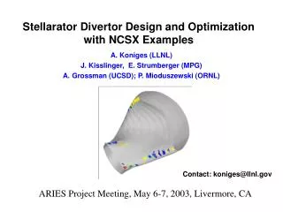
Basic Calculation for K-DEMO Divertor Design June 26, 2013 Kihak IM PPPL-NFRI Meeting, June 26-28, 2013, at PPPL
Procedures to take for Divertor Design
K-DEMO Divertor Concept Definition/Design Procedure • Total Plasma Power, • Power Loss Tree, • SOL , flux expansion …, • Cooling, … • Geometric availability • Establishment of • Divertor main design parameters Plasma Equilibrium Assume DivertorLocation & Shapes Calculation on Heatflux, Particle Flux … (Modeling / Extrapolation ?) ? Heat Transfer / Structural Analyses - Material Assumption(W + Cu tube?) Estimate Plasma-Material Interaction (Erosion, Tritium Retention, …) Documentation on Divertor CSR
K-DEMO Divertor Concept Definition/Design Procedure • Total Plasma Power, • Power Loss Tree, • SOL , flux expansion …, • Cooling, … • Geometric availability • Establishment of • Divertor main design parameters Plasma Equilibrium (edge) Assume DivertorLocation & Shapes Calculation on Heatflux, Particle Flux … (Modeling / Extrapolation ?) ? Heat Transfer / Structural Analyses - Material Assumption(W + Cu tube?) Estimate Plasma-Material Interaction (Erosion, Tritium Retention, …) Documentation on Divertor CSR
K-DEMO Divertor Concept Definition/Design Procedure • Total Plasma Power, • Power Loss Tree, • SOL , flux expansion …, • Cooling, … • Geometric availability • Establishment of • Divertor main design parameters Plasma Equilibrium Assume Divertor Location & Shapes Calculation on Heatflux, Particle Flux … (Modeling / Extrapolation ?) ? Heat Transfer / Structural Analyses - Material Assumption(W + Cu tube?) Estimate Plasma-Material Interaction (Erosion, Tritium Retention, …) Documentation on Divertor CSR
K-DEMO Divertor Concept Definition/Design Procedure • Total Plasma Power, • Power Loss Tree, • SOL , flux expansion …, • Cooling, … • Geometric availability • Establishment of • Divertor main design parameters Plasma Equilibrium Assume DivertorLocation & Shapes Calculation on Heatflux, Particle Flux … (Modeling / Extrapolation ?) ? • Detached Plasma Concept? Heat Transfer / Structural Analyses - Material Assumption(W + Cu tube?) Estimate Plasma-Material Interaction (Erosion, Tritium Retention, …) Documentation on Divertor CSR
K-DEMO Divertor Concept Definition/Design Procedure • Total Plasma Power, • Power Loss Tree, • SOL , flux expansion …, • Cooling, … • Geometric availability • Establishment of • Divertor main design parameters Plasma Equilibrium Assume DivertorLocation & Shapes Calculation on Heatflux, Particle Flux … (Modeling / Extrapolation ?) ? Heat Transfer / Structural Analyses - Material Assumption(W + Cu tube?) Estimate Plasma-Material Interaction (Erosion, Tritium Retention, …) Documentation on Divertor CSR
K-DEMO Divertor Concept Definition/Design Procedure • Total Plasma Power, • Power Loss Tree, • SOL , flux expansion …, • Cooling, … • Geometric availability • Establishment of • Divertor main design parameters Plasma Equilibrium Assume DivertorLocation & Shapes Calculation on Heatflux, Particle Flux … (Modeling / Extrapolation ?) ? Heat Transfer / Structural Analyses - Material Assumption(W + Cu tube?) Estimate Plasma-Material Interaction (Erosion, Tritium Retention, …) Documentation on Divertor CSR
K-DEMO Divertor Concept Definition/Design Procedure • Establishment of • Divertor main design parameters • Total Plasma Power, • Power Loss Tree, • SOL … Plasma Equilibrium Assume DivertorLocation & Shapes • K-DEMO CSR • 1. Overview of K-DEMO • 1.1 … • 1.2 … • … • 3. K-DEMO Tokamak System • …… • 3.4 Divertor • …… • …… Calculation on Heatflux, Particle Flux … (Modeling / Extrapolation ?) ? Heat Transfer / Structural Analyses - Material Assumption(W + Cu tube?) Estimate Plasma-Material Interaction (Erosion, Tritium Retention, …) Documentation on Divertor CSR
1. Power Loss Tree Blanket cooling limit Divertorcooling limit K-DEMO Plasma Power =600 MW Numbers not decided yet
2. Parameter Scope Analysis for Divertor Design(1) SOL power e-foldinglength at midplane * S.C. Jardinet al., Fusion Engineering and Design 80 (2006) 25-62 x (TENTATIVE) (TENTATIVE) q” = - kFMS (25 W/mk) 0.5 MW/m2
2. Parameter Scope Analysis for Divertor Design(2-1) • To reduce Q_div_peak(1/2) • Core radiation fraction • Inboard/outboard ratio (1/8) • (= e-foldinglength) • Target tilting angle ( )- area • Flux expansion factor • Divertor Radiation ratio ☜ Blanket cooling limit ☜ Plasma transport ☜ Plasma behavior/physics Space limitation to locate Divertor Target
2. Parameter Scope Analysis for Divertor Design(2-2) • To reduce Q_div_peak(2/2) • Core radiation fraction • Inboard/outboard ratio (1/8) • (= e-foldinglength) • Target tilting angle ( )- area • Flux expansion factor • Divertor Radiation ratio ☜ Space limitation ☜ Space limitation ☜ Plasma behavior/physics Possible design space for divertor design Reasonable ?! • = 2.5 mm div_rad ~90% • angle ~13o • = 5 mm div_rad ~75% • angle ~20o
2. Parameter Scope Analysis for Divertor Design(3) • To radiate 300 MW out of 600 MW at core plasma (fcore_rad = 50%): • Ar = 1.5% (Zeff ~ 6) • Kr = 0.25% (Zeff~ 4.6) • Neon, Argon too much fuel dilution ~ 7 times comparing with ARIES-AT as K-DEMO: low density (<ne> ~ 1020/m3) while ARIES-AT <ne> ~ 2.15 x 10²⁰/m3 0.25% 1.5%
2. Parameter Scope Analysis for Divertor Design(3) • D, T Radiation • Impurity Radiation : • from D.E. Post et al., “Steady-state Radiative Cooling of • Low Density, High Temperature Plasmas,” • Atomic Data and Nuclear Data Tables 20, 397-439 (1977) Pbrems = 5.35 X 10-37 Z2 neni Psync= 6.18 X 10⁻¹⁷ B2neTe
3. Equilibrium & Blanket/Divertor Radiation Heatload (1) • Plasma equilibrium shape by Chuck was used to get fieldline • for preliminary radiation heatload on divertor and blanket FW
3. Equilibrium & Blanket/Divertor Radiation Heatload (2) • Segmentation of core plasma • for radiation heatload calculation • ARIES-AT MISTRAL Analysis • for impurity transport • Core radiation radial Profile Uniform radiation along leg X-point rad. ~ 10% S.C. Jardinet al., Fusion Engineering and Design 80 (2006) 25-62 Power Loss Tree to give the regional radiation power distribution
3. Equilibrium & Blanket/Divertor Radiation Heatload (3) • Input to Blanket thermo-hydraulic analysis • to determine the max. allowable heatload
4. Preliminary Blanket Thermo-hydraulic Analysis • Blanket TH analysis model schematic view • Radiation heat + Internal Heat by neutron Outlet Temp. 1.5 m long Blanket module A A A 780 C He, 300 C, 8 MPa, 40 m/s Inlet Temp. B B B 0.45 MW/m2 • Radiation heat ONLY FM Steel < 550 C • Radiation heat load on Blanket FW 570 C • Further TH analyses are on-going to reduce blanket structure temperature • to decide the max. allowable radiation heatload on Blanket FW • With varying channel and wall dimensions • With update of neutronicsanalysis
Next Steps …. Various plasma equilibrium calculation with possible divertor geometry in given geometry boundary to locate the divertor targets … Conventional? ? Advanced ? M. Rieth, KIT, IAM-AWP, “Power Plant Divertor Design Options & Materials”, NFRI/KIT Cooperation Meeting, February 14-15, 2013 A.S. Kukushkin et al., Nucl. Fusion 49 (2009) 075008