Download
1 / 66
660 likes | 1.11k Views
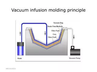
Vacuum infusion molding principle. Vacuum bag infusion – step by step. Vacuum bag infusion. Vacuum infusion with semi-rigid shell. Careful resin flow rate regulation to avoid air entrapment. VOIDS. RESIN FLOW. RESIN FRONT. MSK 2007-11-30. 8. Resin infusion possibilities.

E N D
Careful resin flow rate regulation to avoid air entrapment VOIDS RESIN FLOW RESIN FRONT MSK 2007-11-30 8
Resin infusion possibilities From a centre point towards the periphery SLOWEST! MSK 2007-11-30 9
Resin infusion possibilities From the edge MEDIUM FAST! MSK 2007-11-30 10
Resin infusion possibilities Infusion from the pheriphery FASTEST! MSK 2007-11-30 11
Flexible, semiflexible or rigid mould? MSK 2007-11-30 12 Vacuum bag infusion (flexible bag): suitable for small production volumes, large size products and lower tolerance demands Vacuum infusion with semi-stiff shell: suitable for medium production volumes, medium product size and medium tolerance demands Vacuum infusion/RTM with stiff (solid) moulds: suitable for large production volumes, small size products and high tolerance demands
Blades for wind mills • Length 30 - 70 m • 20 years life length • Lay up of two separate halves which are glued together • Filament winding • Unsaturated polyester, vinyl ester, epoxy resin • Glass fibre, carbon fibre • Stiffness and fatigue properties are important • Denmark major producer
Ambulance Polytec, Sweden
Modular construction design possible • Parts are manufactured separately, and joined by adhesives
Compression molding • A premade compound is formed by pressure in a closed mold • Crosslinking is initiated by heating • Cost effective method for long and very long series • SMC: sheet molding compounds • BMC: bulk molding compounds • Automotive and electrical industry most important application areas
SMC manufacture Shelf life: 3 - 4 months
Compression molding - process conditions • Pressure: 20-50 kg/cm2 • Temperature: 145 - 160 ºC • Time: 1 - 5 minutes • Molds: steel, chrome-plated
Volvo V70 Tailgate Benefits withcomposite compared to steel: • Reduced tooling need • Styling freedom • Integration capability • Weight reduction compared to steel • Technology step
V70 Tailgate M =10,3 kg (structure only) BMC t=3.5, 20% glass SMC t=2.5 (gen. Surfaces) 2.5-4(stressed areas) , 25% glass Reinforcement Directional fibres Glass fiber carpet SMC t=2.5, 25% glass Steel plate Theft/heat protection
Fibre types • Glass fibre: relatively good strength, medium stiffness (E= 70 GPa), transparent, cheap • Carbon fibres: very good strength, high stiffness (E=200-300 GPa), black, very expensive, electrically conducting • Natural fibres: flax, hemp, sisal, wood • Aramid fibres (Kevlar): very good tensile strength, yellow, hard to process, expensive • Special fibres: polyethylene fibres, boron, ceramics, basalt
Fibres, yarns and rowings • An assembly of collimated glass fibres is called a yarn, (tow, strand), and a group of yarns is called a rowing • The yarns and rowings are twisted, which simplifies handling, but makes resin impregnation more difficult • The fibre thickness varies typically between 3-25 µm (commonly 10-20 µm) • Linear densities are given by the TEX number • A rowing has a TEX of minimum 300
Characteristics for glass fibres • Based on SiO2 with added oxides of calcium, boron, sodium, iron or aluminium • Depending on composition different glass types are defined: • A-glass (Alkali glass) • E- glass (Electrical glass) • C-glass (Chemically resistant glass) • S-glass (High strength glass) • Characteristic properties are high strength, good tolerances for high temperatures and corrosive environments • Transparency and no colour are advantages compared to other fibres • Disadvantages are low stiffness, moisture sensitivity and abrasiveness • Low cost has been the most critical factor when promoting their use
Manufacturing process for carbon fibres Polyacrylonitrile (PAN) is the most common precursor for carbon fibres The strength of the fibres are due to orientation and stretching of the C-C bonds Strength can be increased by graphitisation at 1500 ºC
Classification of reinforcements • Short • Unidirectional • 2D weaves/Planar interlaced • 3D/Fully integrated
Different reinforcement types • Chopped strand mat • Continuous strand mat • Woven fabrics, diaxial • Woven fabrics, multiaxial • Stitched fabrics • Braided fabrics • Knitted fabrics • Combinations
Chopped strand mats andcontinuous strand mats • Non-woven structures • Surface weights 150 - 900 g/m2 • Made from chopped or continuous yarns, bound together chemically, mechanically or by heating • Emulsion binders and polyester powder binders are most common • Good drapability • Surface veils (surface eights 10-50 g/m2) are used to get a wanted surface finish • Mats made from other fibres are commonly named non-wovens
Woven fabrics = interlacing of 2 or more yarn systems • Characterised by the crimp • Lower crimp improves formability and resin permeability • Crimp also reduces stiffness plain basket twill satin
Benefits with woven fabrics • Good drapability • Low manufacturing costs due to combination of two layers • Good impact resistance • Lower stiffness due to crimp • Better compression strength
The mechanical properties for weaves depend on: • Type of fibre • Weave structure • Stacking and orientation of fibres • Yarn twist
Braided fabrics • Circular braiding is used for tubes or ropes • Biaxial • Triaxial
Braided reinforcements MSK 2007-11-30 44
Knitted fabrics • Made by knitting • Loose and flexible weaves are produced
Stitched fabrics (noncrimp) • Fibre layers are stiched together into one structure • The stiching is done by sewing • Noncrimp fabrics offer a rapid and precise lay-up of multilayered reinforcement • Different fibre types can be combined, sunh as comingled fabrics
Spread tow fabrics by Oxeon, Sweden Non-crimp fabric
Combinations • Combination of different mats stitched together • Ex: Combiflow mat: • Porous flow layer for better mould filling, used in resin injection
Parabeam – 3 D fabric MSK 2007-11-30 49