Download

1 / 78
780 likes | 936 Views
The Smart Kegerator EE-595 Group 1 Brandon Bartell Nick Sneha Juvekar Anthony Hector. Insert Picture Slide of Group Members Here. Project: Smart Kegerator. Refrigerating, dispensing, and monitoring device for compressed fluids Displays temperature Displays liquid content

E N D
The Smart Kegerator EE-595 Group 1 Brandon Bartell Nick Sneha Juvekar Anthony Hector
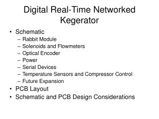
Project: Smart Kegerator • Refrigerating, dispensing, and monitoring device for compressed fluids • Displays temperature • Displays liquid content • Prevents unauthorized usage
Project: Smart Kegerator Temperature sensor Display Signal Conditioner PowerSupply Scale / Converter Keypad/Security Flow solenoid Nick Hector Brandon Sneha Anthony
Performance Requirements • Keypad Matrix: 3 columns, 4 rows • Key Definitions: 0-9 digits, enter, clear • Sensory: Temperature and Weight • Temperature accurate within 0.5 °C • Weight Scale accurate within 0.8 lbs
Performance Requirements • Power Modes: ON/OFF • Power Saving Modes: Standby
Standard Requirements • Operating Temperature Range: 10°C to 32.22°C • Operating Humidity Range: 0-100% Non condensing • Operating Altitude Range: -300ft to 15,000ft • Storage Temperature Range: -50°C to 65°C • Storage Humidity Range: 0-100% Non condensing • Storage Pressure Range: 0.5 to 1.5 ATM • Sources: 120 VAC • Power Consumption: 74 W
Standard Requirements • Volume: 17.6 ft3 • Shipping Container Size: 31in.×68in.×28in. • Mass: fridge plus add-ons • Maximum Parts Count: 50 parts • Maximum Unique Parts Count: 20 parts • Full Warranty Period: 1 years • Service Strategy: Field Repair or Dispose • Product Life: 20 years or more
Key Technical Risk & Problem Areas • These are some key technical risks that we believe might hamper our overall efforts • Sensor interfacing • Programming language selection - integration • Potential long lead time on various components • Size of prototype (transportation, work –space availability) • Component response to low temperatures • Power supply interfacing (step-down transformers, AC\DC conversion) • Signal control and processing • Microcontroller limitations • High costs of components and supplies
EMC Standards • IEC 6100-3-3: Limitation of voltage fluctuations and flicker in low-voltage supplies <16A • Required because a low end voltage flicker could damage the compressor • IEC 6100-4-5: Surge Immunity tests • Required because the microcontroller and other components need to be protected from potential power surges • IEC 6100-4-11: Voltage dips, short interruptions, and variations • Required because brown out conditions will affect keypad thereby affecting overall performance
Safety Standards • CSA C22.2 No. 14-95 • Applies for control and protective devices. Control devices covered in this standard include: pushbutton; flow-, pressure- operated switches; and proximity switches. • IEC 60335-2-34 • Applies for the safety of motor-compressors, their control and protection system which are intended for household purposes. • UL 873 • Temperature-Indicating and -Regulating Equipment: requirements for electrical equipment for control for refrigeration
Specific Safety Requirements • Ground Fault Circuit Interrupter (GFCI) • Connected in series with the power source. Needed because there will be electronics in a potentially wet environment: the sensors near the keg. • Anti-tipping Mercury Switch • If the kegerator tips over, this will turn off the compressor.
Block Prototyping Plan Template • The PCB will have pads and a bus • All socketed components will be soldered or din rail mounted • All Connectors will be IEC, Circular, or PCB mount. • A minimum of 10 components will be used by each block
Block Prototyping Plan Template • Estimation Summary • 1277.8 Estimated vs 400 availability. • $ 674.00 Estimated vs $600 available investment • 3.29 % of total manpower for system design tasks, detailed design tasks, verification tasks, and documentation tasks: • Suggested down/up scope if needed: Added CPLD Control, Electronic Pressure Regulator, Volume/Flow Control
Temperature Sensor Block Owner: Anthony Futterer The purpose of the temperature sensor is to monitor the temperature inside the kegerator unit and serve to inform the user via the display block of the temperature in degrees C.
Performance Requirements • Accurate to 0.5 degrees C. • Provide a user mountable probe device for internal placement. • Provide an inline shielded signal cable for transmittance of the output signal to the signal conditioner. • Provide a separate signal conditioning circuit for output scaling to suitable A/D converter range in display block.
Block Breakdown 4-30 VDC input from power supply AD590 Temperature Sensor Probe Signal Conditioner Interface with display A/D converter
Block Detail Design • AD590M measures temperature in K to 0.5 degrees accuracy. • LM741 and LM1458 Dual Operational Amplifiers serve as signal amplification devices from uA to mA needed. • AD580 high precision voltage comparator serves as error correction tool.
Signal Conditioning Block Owner: Anthony Futterer The purpose of the signal conditioner is to convert the load cell output signal to a usable A/D converter signal amplitude for the display block.
Provide an input port for the signal from the load cell. • Provide an inline shielded signal cable for transmittance of the output signal to the display. • Provide a separate signal conditioning circuit for output scaling to suitable A/D converter range in display block. Performance Requirements
Block Breakdown 24 VDC input from power supply Load Cell Input Connector Signal Conditioning Circuitry Interface with display A/D converter
Block Detail Design • Takes in Load Cell Signal. • LM741 and LM1458 Dual Operational Amplifiers serve as signal amplification devices from uA to mA needed. • AD580 high precision voltage comparator serves as error correction tool.
Reliability Assessment, Growth (Sig-Cond/Temp Sensor Block) • The Team Used the Method B reliability Database • Total from my combined blocks spreadsheet was 343.2078566 • Total MTBF was therefore 0.002393 • The dominant parts of unreliability was the MC1403U Precision Serial Voltage Reference IC • This could be improved by using the AD580 Voltage Reference IC or a similar part with a higher operating temperature than the MC1403U.
Keypad Block Owner: Brandon Bartell • The main purpose of the keypad block is to provide a security feature by making the user enter a 4digit-code. When the code is entered the user will be allowed to pour their drink. • Implementation of a controlling device will also provide metered pouring to either 12 or 16 ounce depending on user selection.
Block Detail Design Anticipated appearance of actual keypad
Block Breakdown In from power supply block Control/Timer Power User interface (Keys) Interface with solenoid block Out to solenoid block
Block Detail Design • The EEPROM memory protects the stored data in case of power failure. • Over 100 million combinations are possible for the user codes. • Two other codes can be used to allow user to get a metered pour of 12 or 16 ounces. • Two separate relay outputs. • Audible key operation - optional
Performance requirements for keypad block Accuracy: -Within .1% to .2% User Indicators: -Indicator Parameter: 3 LEDs. -Applicable User Interface Type: Analog 3x4 keypad matrix -Mechanical Interfaces: Interface with solenoid block via relay signal. -Analog Input Signal Frequency: 67Hz. -Power Signal Input Frequency: 57 – 63Hz.
Standard requirements for keypad block • Min. Operational Ambient Temperature Range: 0 to 50 degree Celsius. • Min. Operational/Storage Ambient Humidity Range: 100 %Rh. • Min. Storage Ambient Temperature Range: -50 to 65 degree Celsius. • Applicable Safety Standards: UL 873. • Applicable EMC Standards: IEC 61000-4-11. • Estimated Max. Production Lifetime: 5 years. • Reliability in MTBF: 0.09 years. • Service Strategy: Repair.
Safety requirements for keypad block • Compliance with IEC61000-4-2 • Compliance with IEC61000-4-3 • Compliance with IEC61000-4-6 • Compliance with IEC61000-4-8 • Compliance CISPR11- RF Emissions
Block Detail Design • Specifications • relay outputs: • output 1: 5 Amp • output 2: 1 Amp, N.C. & N.O. dry contacts, DC 30V max. • operating voltage: DC 12V (DC 10-14V) • current drain: 10 - 100mA • duress output: NPN transistor with open collector output, switches to ground (-) when activated, 100mA/25V DC max. • codes available: User 1 & 2, Super User, Master, Duress and Accelerated codes • code combinations: 111111100 • dimensions: 4.6" x 2.9" x 1.9" • weight: ± 6.5oz (net), ± 8.1oz (gross)
Reliability Assessment, Growth (Keypad Block) • Total FIT’S = 825.2496 • MBTF = 0.00121175 • Dominant unreliable parts are LM741 Op-Amp and Switches • Obvious resolution for unreliable parts is to make the switches waterproof as well as dustproof and of a better quality to increase reliability factors as well as better component selection on the Op-Amp.
Power Supply Block Owner: Hector Gomez The purpose of the power supply is to supply energy to all the blocks. It will also provide overload protection in case of short circuit in the product.
Performance Requirements • To deliver power at +/- 5% of required voltages with low noise. • To supply enough current for all the blocks • To turn off entire blocks with a toggle switch
Block Breakdown Temperature sensor Keypad/Security 120 AC 60HZ PowerSupply AC/DC 120AC 5DC/24DC 3.0 Amp Scale Signal conditioner Display Flow solenoid Hector
Block Detail Design • Transformer steps down voltage • Diode Bridge does the conversion of AC to DC Voltage with 3amps rated diodes and 10% ripple • First phase capacitor used to eliminate transients and makes voltage linear • LM317T regulates voltage and offers current limiting in case of failures in the system.
Block Detail Design • Specifications • operating voltage: 120VAC +/- 10% • 60 Hz Input +/- 3 Hz • Output Voltage DC 5-12V • Output Current 3A • User Interfaces: Toggle switch (to turn off power) • dimensions: 8’’ X 10” • weight: 18oz (net), ± 8.1oz (gross)
Basic Operation • Transformer + Rectifier + Smoothing + Regulator
Complete Rectification 10% ripple, C= (5 X I) / Vs X f C = smoothing capacitance in farads (F)Io = output current from the supply in amps (A)Vs = supply voltage in volts (V), this is the peak value of the unsmoothed DCf = frequency of the AC supply in hertz (Hz)
Reliability Analysis of Power Supply • Total FIT’S : 186.65. • MTBF : 1/186.65= .005 • Dominant part for unreliability is the switch with lambda = 44. • Elimination of mechanical switch will reduce considerable the lambda factor.
Display Block Owner: Sneha Juvekar The purpose of the display block is to convert the analog signal from the signal conditioning block to the digital signal and to display either the temperature inside the kegerator in degree Celsius or weight of the tank in pounds on the 7 – segment LEDs and to eliminate the switch bounce caused by user interface.