LLRF for Chopper
LLRF for Chopper. Grégoire Hagmann Philippe Baudrenghien BE/RF/FB February 24th, 2013. Block Diagram. Plates delay adjustment Monitoring ( Waveform & chopping time) Interlocks. Chopping «pattern». Location “CDU”. Rack AY01. Rack AY01. BIS cables arrivals

LLRF for Chopper
E N D
Presentation Transcript
LLRF for Chopper Grégoire Hagmann Philippe Baudrenghien BE/RF/FB February 24th, 2013
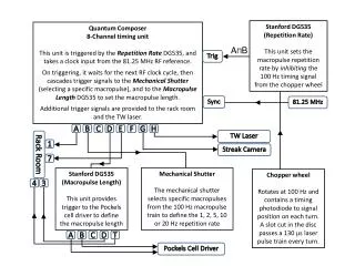
LLRF Linac 4, G.Hagmann Block Diagram • Plates delayadjustment • Monitoring (Waveform & chopping time) • Interlocks Chopping «pattern»
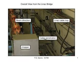
LLRF Linac 4, G.Hagmann Location “CDU” Rack AY01
LLRF Linac 4, G.Hagmann Rack AY01 • BIS cables arrivals • Need of space fortransition patch panel : 2U • Need 1U Beam permit patch =>TE/MPE/EP • Need 1U User permit parch Who? BE/RF or TE/MPE? • Position for BIS patch-panels? DRAFT Transition patch needed No Burndy on VME board
LLRF Linac 4, G.Hagmann Chopper Limitations • Max Chopper pulse length : 500us (programmable) • => need monitoring (start counter at “source on”) • => Drive off when “source off” • => Drive off when >500us (timeout) from “source on” • => What if timeout? Alarm? User Permit False? OP action? <500us
LLRF Linac 4, G.Hagmann Ring blanking Discussion with A.Blas • Compatible with booster? (Magnetic compensation in RF lowlevel…) • Reaction time for ring interlock?
LLRF Linac 4, G.Hagmann Ring blanking During the Linac 4 pulse (window), Can one ring be inhibited? And does it need immediate action? If YES : • “Dynamic”Ring blanking • Need timing ring identification • Need 1 chopping pattern table per ring • Need accurate HW timing(s) for re-synchronization If NO : Can 1 ring interlock be interpreted like a change in nb of turn of the ring? If YES: • High level software re-compute chopping pattern (new settings) • Load of the new chopping pattern and played for next cycle/user If NO: • No change in chopping pattern table • Need ppm information for which ring are “played” (Timing or with Software)
LLRF Linac 4, G.Hagmann L4-Booster synchronization Beam must be chopped during the 1us PSB ring change References document : • Synchronization between Linac4 and the PS BoosterCERN-ATS-Note-2010-052 2 solutions : • Synchronization for every Ring • “Dynamic” ring blanking feasible • Accurate synchronization signals => accuracy? • 1 “pattern” table for every ring • Table switching • 1 single synchronization after “Source On” timing start • No “Dynamic” ring blanking (or more complex => to be studied) • 1 accurate synchronization signal • 1 “pattern” table for all rings • No distinction if 1 or more ring => “just” one chopping pattern RF frequencies (L4 & booster) stability? TRF ≈ 2.84ns RF Linac4 HW timing Tr << TRF
LLRF Linac 4, G.Hagmann L4-Booster synchronization Re-synchronization for every ring (Meeting Dec 16th 2011) 3 Proposals : • 4 timings CTRV (next Ring identifier) • 1 accurate HW timing at every ring start • Dynamic ring blanking feasible • Safer, consistency between Chopper and PSB injection Distributor • 4 accurate HW timings, 1 per ring (ring start) • Dynamic ring blanking feasible • HW More complex, More cabling • 1 timings CTRV (source on) • 1 accurate HW timing at the window start (linac 4 pulse) • 1 pattern table for 4 rings • No Dynamic ring blanking • Need new setting (at the next cycle) for new pattern
LLRF Linac 4, G.Hagmann L4-Booster synchronization exemple • 4 timings CTRV (next Ring identifier) • 1 accurate HW timing at every ring start • Dynamic ring blanking feasible • Safer, consistency between Chopper and PSB injection Distributor Ring 1 start Ring 2 start Ring 3 start Ring 4 start HW timing
LLRF Linac 4, G.Hagmann CDU details
LLRF Linac 4, G.Hagmann Start & Stop independentadjustabledelays for all plates CDU details From & To BIS(No fiberanymore) Monitoring, Gating, etc. RF Interlock crate
LLRF Linac 4, G.Hagmann CDU details • VME board “RF” type • BIS input & output on LEMO • EPG.0B.304.HLN (or similar) • XXX.1B.308.XXX • RF Interlock • 1 interlock or 2 interlocks (1 per chopper) ? • From AY01 • Optical, Multi-mode, ST • Same for cavity-controller PIMS, CCDTL…) • TX pulses monitoring • Veto • Diagnostics
LLRF Linac 4, G.Hagmann BIS «gating» • Gating with timing from BE/CO (CTRV) ? • Fail safe? • Gatingrather in the BIS than CDU ? Gating ON Gating OFF Chopper forced OFF BIS even unlatched BIS event Latched
LLRF Linac 4, G.Hagmann New special «BI» timing • Addition of a new «CTRV like» timing feasible • Not fail safe • 2 solutions: • Implemented HW similar to the BIS signal • => Fixed implementation • => Simple functionality • => “Robust” • => Timing always needed • Through FPGA • => Flexible implementation • => Complex functionality possible • Timing Hardware?
LLRF Linac 4, G.Hagmann New special «BI» timing Chopper ON Chopper OFF Chopper ON (latched)
LLRF Linac 4, G.Hagmann RF Interlock Power side (PLC) : « Phoenix contact » module open (example of a design) « Phoenix contact » module closed • LowLevel side : • ST optical receiver on CDU board • By-pass input foreseen for “debug & tests”