Exploration of BSP Trees for Spatial Partitioning
Discover the versatility and efficiency of Binary Space Partitioning (BSP) Trees in collision detection and solid representations. Learn how BSP trees divide space with dividing planes and handle internal and external geometry distinctions.

Exploration of BSP Trees for Spatial Partitioning
E N D
Presentation Transcript
2.8.Binary Space Partitioning Trees Exploration of BSP trees
BSP Trees Overview of binary space-partitioning trees
BSP Tree Hierarchies A binary space-partitioning (BSP) tree recursively partitions space into pairs of subspaces with respect to dividing planes of arbitrary position and orientation. The two partitions are referred to as the positive and negative halfspaces (respectively in front of and behind the dividing plane). A BSP tree is a versatile data structure, capable of performing the same tasks as a k-d tree or octree (but not vice versa). The BSP tree can also be used to provide boundary/solid representations of arbitrary polyhedral scenes.
BSP Tree Hierarchies BSP trees are very versatile in collision detection as they can provide both a spatial partitioning (a nonboundary representation) and a volume representation (a boundary representation, for a solid object). As a volume representation, BSP trees can be used to represent and distinguish the interiors of polygons and polyhedra from their exteriors.
BSP Tree Hierarchies The left figure provides an example of spatial partitioning (with a typical lookup cost of O(log n)). The right figure shows how a BSP tree can map out the exterior/internal of a polygonal object. When, as illustrated, the dividing planes are selected to match the faces of the input geometry it is termed autopartitioning(or polygon aligned). In contrast, dividing planes coplanar to the xy, xz, or yz planes are called axis aligned. Dividing planes that have no restrictions put on them (nor on the partitionings they form) are called arbitrary or general. • Aside: BSP trees using only axis-aligned dividing planes are k-d trees.
Types of BSP Tree: Leaf storing A leaf-storing (or leaf-based) BSP tree stores geometry in the leaves of the tree (rather than in the internal nodes). Each internal node only contains the dividing plane and references to the child subtrees. The dividing planes of leaf-storing trees can be either arbitrary or autopartitioning. An example leaf-storing tree is shown using arbitrary positioning. • Aside: When autopartitioning, all faces coplanar with a selected dividing plane are marked to ensure they are not used when selecting future dividing planes.
Types of BSP Tree: Solid Leaf Solid-leaf BSP trees are built to represent the solid volume occupied by the input geometry, i.e. dividing planes are selected to separate the solid volume from the exterior of the object. No geometry is stored in the tree, with leaf nodes only indicating if the area in front and behind of the dividing plane is empty or solid. Consider the example in which a solid-leaf BSP tree is constructed to represent the interior of a concave (dart-shaped) polygon. Solid-leaf BSP trees are useful for collision detection as there is no need to perform specific polygon tests (no polygons are explicitly stored).
Building a BSP Tree Overview of how a BSP tree can be constructed
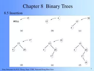
Building the BSP tree Building a BSP tree (either from scratch or recomputing parts of a tree) is computationally expensive, i.e. BSP trees are typically pre-computed and hold static background geometry (moving objects are handled using some other approach). Building a BSP tree involves three steps. Selection of a partitioning plane. Partitioning input geometry into the positive and negative halfspaces of the dividing plane. Geometry that straddles the plane is split to the plane before partitioning. 3. Recursively repeat the above steps for each subtree until some termination condition is reached.
Building the BSP tree Recursively build a leaf storing BSP using the input list of polygons (depth initially equal to o) BSPNodeBuildBSPTree(List<Polygon> polygons, int depth) { if (polygons.empty()) return NULL; if (depth >= MAX_DEPTH || polygons.Count <= MIN_LEAF_SIZE) || etc. ) return new BSPNode(polygons); Plane splitPlane = PickSplittingPlane(polygons); List<Polygon> frontList = new List<Polygon>(); List<Polygon> backList = new List<Polygon>(); for (inti = 0; i < numPolygons; i++) { switch (ClassifyPolygonToPlane(polygons[i], splitPlane)) { // -> ... } } BSPNodefrontTree = BuildBSPTree(frontList, depth + 1); BSPNodebackTree = BuildBSPTree(backList, depth + 1); return new BSPNode(frontTree, backTree); } If no more polygons are available, then return If leaf creation criteria is met, then create leaf node Select the partitioning plane based on the input geometry Test each polygon against the dividing plane, adding them to their forwarding list(s) Recursively build child subtrees and return the combined node For a leaf-storing tree, coplanar polygons can be sent to either side, to the front in this implementation. case COPLANAR_WITH_PLANE: case IN_FRONT_OF_PLANE: frontList.AddAtBack(polygons[i]); break; case BEHIND_PLANE: backList.push_back(poly); break; case STRADDLING_PLANE: Polygon frontPart, backPart; SplitPolygon(polygons[i], splitPlane, out frontPart, out backPart); frontList.AddAtBack(frontPart); backList.AddAtBack(backPart); break; Straddling polygons are split, with a part sent to each side
Building the BSP tree The PickSplittingPlane() function is non-trivial if a good partitioning plane is to be selected. The condition under which tree construction halts depends on the type of tree. For a solid-leaf tree construction proceeds until the set of remaining input polygons becomes empty. A leaf-storing BSP tree is typically stopped when: The leaf contains less than some preset number of polygons. A fixed cutoff depth has been reached. A good dividing plane cannot be found.
Selecting Dividing Planes The dividing planes selected during tree construction greatly effects the size and shape of the resulting tree (and hence performance and memory). Typically good results can be obtained by trying a number of candidate dividing planes at each level of the tree, picking the one that scores best according to an evaluation function If using autopartitioning then the search is restricted to the supporting planes of the faces in the input geometry. Whilst simple to implement, autopartitioning may produce more splitting than desired in leaf-storing trees – e.g. consider the autopartitioning of a polygon sphere (all convex faces will lie on the same side of the plane, with a resultant tree depth equal to the number of sphere faces!)
Selecting Dividing Planes A good approach of handling detailed objects within a scene, is to use bounding volume approximations of the objects and autopartition through the faces of the bounding volumes before performing any splitting involving the geometry within the bounding volumes. Alternative candidate dividing planes can include planes in a few predetermined directions (e.g. coordinate axes) or evenly distributed across the extents of the input geometry (i.e. forming a grid across the geometry). Arbitrary planes can also be selected through a hill-climbing approach whereby, repeatedly, a number of slightly different planes to a candidate plane are tested to determine the new candidate plane.
Evaluating Dividing Planes Evaluation criteria of use to collision detection includes picking planes so as to minimize splitting of geometry (least-crossed stragegy) or to attempt to balance the geometry equally on both sides of the splitting plane. The approaches tend not to be complementary, with a strong focus on one criteria likely to provide poor performance in the other criteria. A weighted linear combination of the two is often used in practice (with reduced splitting often weighted higher than balancing). Line A minimises split polygons; Line B balances the number of polygons; Line C represents a compromise.
Classifying Polygons with Respect to a Plane When building a BSP tree, all polygons need to be partitioned with respect of a dividing plane into those that: lie in front of the dividing plane. lie behind the dividing plane. straddle the dividing plane. lie coincident with the dividing plane Whilst mathematically straightforward, inaccuracies in floating-point arithmetic entail that a split polygon may still be found to straddle the dividing plane. A practical solution to this problem is to use thick planes defined as n • (X − P) < ε (for some ε), i.e. all points within a small distance of the plane are considered lying on the plane.
Splitting Polygons Against a Plane During BSP tree construction, when a polygon is found straddling a dividing plane it must be split in two. Clipping a polygon against a plane is done using the Sutherland–Hodgman algorithm. The algorithm considers one polygon edge at a time and returns a set of points based on an intersection test between the edge and plane. • Aside: Why is splitting needed? Consider the figure. • If T is not split on partition 1 (and is sent down both sides), then in split 2 T is (incorrectly) found to be on both sides (and would end up in leaf C), i.e. clipping is needed to prevent incorrect assignment.
Splitting Polygons Against a Plane Whilst polygons are split during the construction of the tree, this need not mean that the polygon fragments ending up in the leaves must be the polygons output in the final tree. For collision detection, it is better to store a reference to the original polygon with each fragment generated during splitting. In the leaves, the reference is output, and not the fragment. • Aside: The normal Sutherland–Hodgman algorithm simply discards any part behind the cutting plane, i.e. a modified version is needed for BSP tree construction that will return the portion behind the plane. Additionally, the algorithm should also be mindful of any thick plane assumption introduced to prevent floating point inaccuracies.
Using a BSP Tree Overview of how a BSP tree can be used
Testing a Point Against a Solid-leaf BSP Tree Determining if a point lies in empty or solid space of a solid-leaf BSP tree can be done by evaluating the point with respect to a node’s dividing plane. The side on which the point falls determines which child node is next visited. Traversal continues until a leaf node is reached. The value of the leaf node answers the query. If the tested point lies on the boundary of a solid volume represented by the BSP tree then both subtrees should be explored. When both subtrees are traversed if different results are returned (e.g. solid and empty) then the point lies on the boundary (a matching return from both subtrees is simply returned).
Testing a Point Against a Solid-leaf BSP Tree HitTypePointInSolidSpace(BSPNode node, Point p) { while (!node.IsLeaf) { float dist = Dot(node.Plane.n, p) – node.Plane.d; if (dist > EPSILON) { node = node.Child[0]; } else if (dist < -EPSILON) { node = node.Child[1]; } else { HitType front = PointInSolidSpace(node.Child[0], p); HitType back = PointInSolidSpace(node.Child[1], p); return (front == back) ? front : HitType.OnBoundary; } } return node.IsSolid ? HitType.Inside : HitType.Outside; } Determine the distance the point is from the plane If the point lies in front of the plane, then visit the first subtree, else if behind the plane, then visit the second subtree If the point lies on the dividing plane then visit both subtrees If the returned results differ, then return that the point is on the boundary If a leaf node has been reached then return it’s recorded type
Intersecting a Ray Against a Solid-leaf BSP Tree When testing for intersection of a ray or segment against the tree care must be exercised to ensure that the tested ray or segment is not repeatedly subdivided against the splitting plane (as repeated subdivision can introduce drift due to accumulated floating point inaccuracies). A better approach is to determine the intersection ‘time’ of the ray against the plane (R(t) = P + td, tmin ≤ t ≤ tmax). The time thit of the first intersection with a solid leaf is returned (should an intersection be found). Aside: If thick planes are used, then an epsilon term needs to be added to the plane intersection tests, with both sides explored given plane intersection.
Testing a Ray Against a Solid-leaf BSP Tree HitTypeRayIntersect(BSPNode node, Point p, Vector d, float tmin, float tmax, out float thit) { Stack<BSPNode> nodeStack; Stack<float> timeStack; while (true) { if (node.IsLeaf == false) { float dist = node.Plane.d - Dot(node.Plane.n, p); intnearIndex = dist > 0.0f ? 1 : 0; float denom = Dot(node.Plane.n, d); if (denom != 0.0f) { float t = dist / denom; if (0.0f <= t && t <= tmax) { if (t >= tmin) { nodeStack.Push(node.Child[1 ∧ nearIndex]); timeStack.Push(tmax); tmax = t; } else nearIndex = 1 ∧ nearIndex; } } node = node.Child[nearIndex]; } Determine if the ray (or segment) intersects with solid geometry. If available, also return the ‘time’ of intersection thit(where R(t) = p + t*d, tmin <=t <=tmax). Define two stacks to hold ‘recursive’ information Find the side of the splitting plane on which the ray starts Determine the direction of the ray relative to the plane (a value of 0.0 denotes a parallel ray – in which case the side of the plane the ray lies will be followed) Determine the ray ‘time’ of intersection A straddling ray has been detected, i.e. push far side onto stack and visit near side If 0 <= t < tmin, then visit far side
Testing a Point Against a Solid-leaf BSP Tree else { if (node.IsSolid) { thit = tmin; return HitType.Inside; } if (nodeStack.empty()) break; tmin = tmax; node = nodeStack.Top(); nodeStack.Pop(); tmax = timeStack.Top(); timeStack.Pop(); } } return HitType.Outside; } A leaf node has been reached. If it is solid, then record a hit at tmin If no more subtrees remain to be considered, then exit, otherwise pop the topmost node from the stack and continue. If reaching here, no solid leaf node could be found.
Directed reading Directed Reading Directed mathematical reading
Directed reading Read Chapter 8 of Real Time Collision Detection (pp349-381) Related papers can be found from: http://realtimecollisiondetection.net/books/rtcd/references/ Directed reading
Summary Today we explored: • How to build and use a BSP tree To do: • Read the directed material • After reading the directed material, have a ponder if this is the type of material you would like to explore within a project.