Download
1 / 46
460 likes | 604 Views
Enhancing Energy Efficiency of Built Environment through Daylighting. Ir. Yiu-chung WU Senior Building Services Engineer The Government of the Hong Kong SAR Dr. Danny H.W. LI City University of Hong Kong. Enhancing Energy Efficiency of Built Environment through Daylighting.

E N D
Enhancing Energy Efficiency of Built Environment through Daylighting Ir. Yiu-chung WU Senior Building Services Engineer The Government of the Hong Kong SAR Dr. Danny H.W. LI City University of Hong Kong
Enhancing Energy Efficiency of Built Environment through Daylighting Daylight through Light Transportation System Daylight through Window
Light Transportation Systems Sun Pipe System Hybrid Solar Lighting System
Sun Pipe System Design Concept Tubular skylight with reflective pipe Collects daylight on rooftop Guides daylight down Diffuses daylight into the building interior
Sun Pipe System Components Dome consists of clear polycarbonate curved reflector to capture daylight and light intercepting transfer device to redirect daylight increases the daylight collection and harvest for low sun angles
Sun Pipe System Components Pipe consists of a very high reflective internal finish with 98% to 99.7% reflectance straight run or with elbow to convey daylight
Sun Pipe System Components Ceiling diffuser
Sun Pipe System Performance Depends on location climate weather
Sun Pipe System Performance Limitation in vertical length 530mm – 13m 350mm – 10m 250mm – 6.5m horizontal run not recommended one dome supplies one diffuser point only
Sun Pipe System Case Study Electrical and Mechanical Services Department Headquarters 10 nos. 250mm sun pipe at a corridor on the top floor artificial lights (CFT) to back up
Sun Pipe System Case Study Diffusers
Sun Pipe System Case Study Domes
Sun Pipe System Case Study Diffuser of sun pipe (right) Artificial light (left)
Sun Pipe System Case Study Results of half months’ measurements in December 2005
Sun Pipe System Observation and Discussion To be installed with artificial lighting with photo sensor Can direct daylight to more interior areas; and can provide more stable and uniform artificial daylight than skylight Recommended for obvious energy and environmental benefits Initial cost is not very attractive and competitive at present; but expected to be lower after further development and advancement of material and equipment
Hybrid Solar Lighting System Design Concept and Case Study Sacramento Municipal Utility District • 1200mm diameter roof-mounted solar collector to concentrate daylight into a bundle of optical fibres
Hybrid Solar Lighting System • Infra-red and ultra-violet filter to filter out unwanted heat to the interior which can further save energy for cooling Design Concept and Case Study
Hybrid Solar Lighting System • Automatic sunlight tracking system to rotate the collector to collect maximum sunlight Design Concept and Case Study
Hybrid Solar Lighting System • require a small penetration through the roof • allow light transmitted around and through complex building environment with bents of any angles Design Concept and Case Study The optical fibres are very flexible and configurable, hence
Hybrid Solar Lighting System • A bundle of 127 nos. optical fibres connecting the solar collector to the hybrid lighting fittings with a running length of 20m Design Concept and Case Study
Hybrid Solar Lighting System • 3 nos. fluorescent fitting each with 3 nos. 1200mm T8 tube and 2 nos. emitting rods each connected with 15 nos. of optical fibres • 3 nos. 20W halogen spot light and 3 nos. incandescent lamp bulb each connected to 4 nos. of optical fibres Design Concept and Case Study Hybrid lighting fittings connected
Hybrid Solar Lighting System • On a sunny day, the system can deliver 50,000 lumens (equivalent to 55 nos. of 60W incandescent lamps) Design Concept and Case Study
Daylight through Light Transportation System Conclusion Various light transportation systems are available in the market which can transmit daylight effectively and efficiently Two most mature systems are discussed, both of them have their pros and cons Designers are encouraged to adopt the kind of system that suits their application to best use of daylight to achieve energy saving
Daylight through Window Daylight is the best light source in the form of renewable energy Lighting control by photo sensors with dimmers becomes mature Proper lighting control integrated with daylight can reduce artificial lighting energy effectively Prediction of indoor daylight illuminance is critical in the design of lighting control to achieve most optimal energy saving
Simplified Daylight Illuminance Prediction Method Prediction of daylight illuminance is very complicated Simulation computer software tools available are too sophisticated and time-consuming to run A simple software tool would be very useful especially during preliminary design stage with different conceptual design schemes are being considered
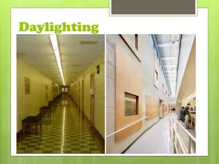
Importance of Daylighting • Daylighting is an effective approach to have a more flexible building façade design strategy • Enhance a more energy-efficient building design (always an energy saver) • Provide visual comfort • Greener building development • People desire good natural lighting in their living and working environments
Estimation of daylight illuminance • A key step in evaluating daylighting performance • Once the daylight illuminance obtained, it is quite straightforward to compute the lighting energy savings • The presentation mainly for the indoor daylight illuminance estimation
Prediction method • Traditional daylight factor approach • Based on CIE standard overcast sky only • Simple • Not flexible :Cannot cater for the dynamic variation of daylight illuminance for different solar positions under non-overcast sky conditions
The CIE Standard Skies • In 2003, the International Commission on Illumination (CIE) has adopted 15 standard skies • Containing 5 clear, 5 partly cloudy and 5 overcast skies • Covering the whole spectrum of usual skies found in nature
The CIE standard skies • The relative luminance distribution, lv, for a standard sky combining gradation function (Z) and indicatrix function f()
The CIE standard skies • gradation function (Z) • indicatrix function f()
The CIE Standard Skies • Classify the CIE standard skies for Hong Kong • Measured sky luminance were compared with modeled standard sky models to determine the root-mean-square error (RMSE): • The standard skies classified with the lowest RMSE
The CIE standard skies • Standard sky numbers 1 (overcast) and 13 (clear) are of the highest frequency of occurrence
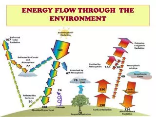
Methodology • For daylight prediction, three components are involved • Sky component (SC) • Externally reflected component (ERC) • Internally reflected component (IRC) • Only SC and IRC are considered in this program : • For buildings facing small sky obstructions such as top floors in high-rise blocks or buildings located in low density business areas
Methodology • Internal daylight illuminance depends on the outdoor illuminance and exact sky luminance distribution at that time • The approach: relates the luminance distribution of the sky to the illuminance at a point in a room
Sky Component • is the sum of the sine function of the elevation for each the sky element that is seen by the reference point times solid angle times angle between the sky element and the line normal to the window facade • For those sky element which can be “seen” by reference point, it can expressed as:
Internally reflected component Lighting coming directly from the sky C1 Reflected lighting coming from below the horizon C2
Internally reflected component • A = the total area of all the interior surfaces • R = the average reflectance of all the interior surfaces • Rcw = the average reflectance of the ceiling and upper walls above the mid-height of the window • Rfw = the average reflectance of the floor and lower walls below the mid-height of the window • τ = the overall transmittance of the window • W = the window area • (i.e. they are building parameters)
Internally Reflected component C1 is the ratio of illuminance received by vertical window to the horizontal diffuse illuminance, Evd : (For 0≤θ<π/2, -π/2<Φ-Φn<π/2; =0 otherwise) C2 : For non-overcast sky: For overcast sky:
Calculation Sequence Devise a set of factors for sky and Internally Reflected components Calculate a sky luminance distribution pattern Calculate hourly daylight level of a typical day of each month Predict lighting power consumption
Input and output of software Illuminance Database Building Geometry Indoor Illuminance level Software Tool Surface Reflectance Lighting Power Consumption Lighting Properties Lighting Energy Saving
User Interface Surface reflectance Lighting Inputs Building Geometry
A Case Study External conditions and room parameters for validation:
Validation • For sky type 1, the estimated value by the software is 4.89% while RADIANCE is 4.32, the discrepancy is less than 0.6%. • The prediction by the software is slightly smaller than the prediction by RADIANCE. • The peak different between the software prediction method and RADIANCE is only 2.7% (for clear sky 13). • Using traditional CIE overcast sky pattern only would considerably underestimate the interior daylight illuminance.
Conclusions • The software can be used to estimate the indoor daylight illuminance and hence the likely electric lighting energy savings under CIE standard skies 1 and 13. • The software is convenient for architect and building engineers during initial design stage when different schemes and concepts are being considered
Enhancing Energy Efficiency of Built Environment through Daylighting Thank You