Download
1 / 73
730 likes | 872 Views
Today Finish cable modem Cell phones Start link layer!. TDM vs FDM. FDM. TDM. Time Division Multiplexing (TDM). channel 1. channel 2. channel n. FDM. Channel 1. Channel 2. Channel n. very high bandwidth (fiber). Head end. coaxial. fiber. Internet over Cable.

E N D
Today • Finish cable modem • Cell phones • Start link layer! University of Delaware CPEG 419
TDM vs FDM FDM TDM University of Delaware CPEG 419
Time Division Multiplexing (TDM) channel 1 channel 2 channel n University of Delaware CPEG 419
FDM Channel 1 Channel 2 Channel n University of Delaware CPEG 419
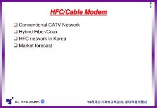
very high bandwidth (fiber) Head end coaxial fiber Internet over Cable A group of homes share the cable. (As oppose to DSL.) The number of homes per group is around 500-2000. University of Delaware CPEG 419
Cable Spectrum 108MHz Upstream 5 – 42 MHZ 750MHz 550MHz TV shopping HBO Downstream data TV FM 54 MHz 88MHz Each TV channel gets its own frequency. This is called frequency multiplexing University of Delaware CPEG 419
Cable Modem • Why put downstream data at highend of spectrum? • When they made the system they put in amplifiers that could work at these high frequencies (why?) • So the downstream was all set to go. But upstream amplifiers had to be installed. • Downstream data also uses FDM: 6MHz or 8MHz channel width with QAM-64 (what is the data rate?) (This should be 6Mbaud – 8Mbaud) • But with overhead you only get 27Mbps. • The upstream also uses FDM, but with QPSK (2 bits per symbol). University of Delaware CPEG 419
Use 2400 sample each way - duplex Definition: a duplex connection means that we can send data in both directions at the same time. A simplex or half-duplex connection only sends data in one direction at a time. How fast is V32? The phone system transmits 300 to 3400 Hz So what bandwidth can we use. How fast can we send symbols? We can send signals at 3100*2 = 6200 baud. We need to send signal two ways, so we can at most send 3100 baud. But there needs to be a guard band (so they don’t overlap). So 2400 baud is used. So 2400 * 6 = 14400 bps What is the baud rate? V.34 2400 baud - with 12 data bits/symbol V.34 bis 2400 baud – with 14 data bits/symbol That’s the fastest there is! To get 56K you send at 4000 baud (if the phone system can handle it) University of Delaware CPEG 419
DSL A total of 256 4kHz channels so 8 kBaud per channel Upstream downstream empty 25kHz (channel 6) channel 6+32 Voice POTS (stands for ?) (channel 0) 250 parallel channels: Each data channel uses QAM 16 (with 1 parity bit). The quality of each channel is monitored and adjusted. So channels may transmit at different speeds What is the maximum data rate? University of Delaware CPEG 419
Cable modems • On modem boot-up, the head-end tells the modem which channel (time and frequency) to use for upstream and downstream transmission. • Many users may share the same channel. • To share the same channel, cable uses time division multiplexing (TDM) and media access control (MAC). University of Delaware CPEG 419
Back to Cable • Downstream is easy. The head-end just transmits packets as it wants. Each packet has a label, so the modem can detect that the packet belongs to it. • Upstream is hard. • The upstream channel is shared. • TDM is used, but still each TDM slot is shared by many users. • What happens if two users try to send upstream data on the same channel? University of Delaware CPEG 419
Cable: Upstream Media Access (link layer) • Time is divided into minislot. It is possible to transmit 8 bytes in one minislot. • The modem asks the headend if it can transmit a packet. • The headend responds with an acknowledgment and tells the modem which minislots it can use. • Problem: How can the modem sent the request without permission to use minislots? • Solution: on boot-up, the headend tells the modem which minislots it can use for requesting minislots and the headend never allocates these minislots for upstream data. • Problem: These special control minislots are shared by many users (why?), so what happens if two users make a request at the same time? • Solution: If two users transmit at the same time, the signal cannot be understood by the headend and is ignored. Thus, no acknowledgement is made. The competing modems then wait a random amount of time and try again. It if fails again, then they wait a random amount of time again, but the maximum time they might wait is doubled. University of Delaware CPEG 419
Cable MAC (media access control ) headend modem minislot } modem sends a request for upstream minislots Headend gets request. Thinks about it. And sends acknowledgement with which minislots to use. modem sends data data does not overlap with request minislot upstream request for bandwidth minislots time University of Delaware CPEG 419
Cable MAC: Contention Two modems send request for bandwidth at the same time. The headend can figure out what was transmitted and ignores it The modems wait for the acknowledgement that will never arrive. The amount of time they wait is random. This time the red modem gets through. The blue modem tries again, but the green modem also sends a request. Now the blue doubles the maximum random amount of time it waits before sending another request. Green gets through University of Delaware CPEG 419
Cable vs. DSL • Cable could give higher bandwidth, but it might give less. It depends on the number of users. • If there are too many users in a group, the cable operator has to put in a fiber and headend. That cost money, so they try not to do it. • DSL can promise 1Mbps down and 256kbps up, and you will likely get it. • Note that sharing bandwidth is much more efficient than assigning each user a fixed chunk. • The telephone system is very reliable. When was the last time you picked up the phone and there was no dial tone (major earthquake or huge storm). Cable will go down when the power goes out. University of Delaware CPEG 419
A F D E E B G G C C A F F D E Mobile Phone • One transmitter/receiver in each cell. • The base station transmit at very high power and has sensitive receivers. This way the cell phone can broadcast at low power and have a simply receiver. • The size of the cell depends on the transmitting power of the base station. • In first generation phones, there were 832 channels. Each channel was 30kHz. (which kind of multiplexing?) • Multipath reflections are a problem. • Each cell uses a different set of channels (why?) • What to do if there are more users in a cell? University of Delaware CPEG 419
1 1 2 2 3 3 4 4 5 5 6 6 2nd Generation Mobile Phones • Types of 2nd generation phone systems: D-AMPS, GSM, CDMA and PDC. (PCS is second generation, but not a standard like these, just mean second generation) • All Digital • Phone is recorded by phone, converted to digital and compressed. The compressed signal (numbers) are sent to the base station. • Now a single 30KHz channel can be shared by 3 users using TDM. 40ms 1 slot: 324 bits 64 bits control 101 bits of error correction 159 bits of data from mobile to base 1850.01MHz from base to mobile 1930.05MHz University of Delaware CPEG 419
GSM • Widely used outside the US (but some here as well). • Similar to the D-AMPS, but much higher bandwidth, 200kHz vs. 30kHz. • There are 992 time slots. • Max data rate is 33.854 kbps. After overhead and error correction, there is 13kbs of speech data. • D-AMPS is 8kbs of speech data. University of Delaware CPEG 419
CDMA – Code Division Multiple Access • Verizon and Sprint uses CDMA. AT&T uses D-AMPS. • D-AMPS and GSM use FDM and TDM. CDMA is totally different. And is the best. • All users transmit over the same frequencies at the same time!?! • Idea: each phone uses a different code. • If you listen on the wrong code, it sounds like noise. If you listen on the right code it sounds like the right signal (with the other transmissions sounding like noise). University of Delaware CPEG 419
CDMA • Each bit is transmitted into m short time intervals called chips. • Each user has a unique m-bit chip sequence. • To send a 1, the user sends the sequence. To send a 0, the user sends the complement. A: -1 -1 -1 +1 +1 -1 +1 +1 A (zero): +1 +1 +1 -1 -1 +1 -1 -1 A (one): -1 -1 -1 +1 +1 -1 +1 +1 University of Delaware CPEG 419
CDMA A: -1 -1 -1 +1 +1 -1 +1 +1 B: -1 -1 +1 -1 +1 +1+1 -1 C: -1 +1 -1 +1 +1 +1 -1 -1 D: -1 +1 -1 -1 -1 -1 +1 -1 codes A(1): -1 -1 -1 +1 +1 -1 +1 +1 B(1): -1 -1 +1 -1 +1 +1+1 -1 C(0): +1 -1 +1 -1 -1 -1 +1 +1 D(1): -1 +1 -1 -1 -1 -1 +1 –1 Total:-2 –2 0 -2 0 -2 +4 0 Send: A=1, B=1, C=0, D=1 received signal University of Delaware CPEG 419
CDMA Total: S = [-2 –2 0 -2 0 -2 +4 0] (S A)/8 =(-2*-1 + -2*-1 + 0*-1 + -2*+1 + 0*+1 + -2*-1 + 4*+1 + 0*+1)/8 =(2+2-2+2+4)/8=1 Idea: A, B, C and D are orthonormal set of vectors: (A B)/8 = 0, (A C)/8 = 0, (A D)/8 = 0, (B C)/8 = 0, (B D)/8 = 0, (C d)/8 = 0, orthogonal normalized (A A)/8 = 1, (B B)/8 = 1, (C C)/8 = 1, (D D)/8 = 1 University of Delaware CPEG 419
FDM Code is sin(wi t) Send code*Value. (e.g., 14.967384 sin (wi t)) Total sent signal = How to decode? The Fourier expansion is an orthogonal decomposition. Each channel sends one (or a few) elements in the decomposition. The Fourier transform can decompose the signal to get the components (channels). University of Delaware CPEG 419
3G (third generation phones) • They expect • more data than voice (we’ll see) • Upper maximum data rates: 2Mbps while stationary, 384kbps while walking, and 144kbps while driving. (we’ll see). • High-quality voice transmission (never! – blade runner) • Messaging (no sweat) • Web surfing (ok) • Multimedia (at 144kbps?) University of Delaware CPEG 419
3G ideas • Seamlessly move from cell to cell. Currently, when you leave a cell, you are dropped but the transmitter and quickly find a new one (maybe). • GPRS (general packet radio service) - Packet network over the network. University of Delaware CPEG 419
Packet Switched Network vs Circuit Switched Network • Circuit switched – each connection gets bandwidth (or time slot) and uses this at will (or not). The connection is maintained for the duration of the connection. • Packet switched – Every bit of data is clumped together (packet) and sent into a large network. The packet has an address that tells the network where the packet goes. University of Delaware CPEG 419
Circuit switched That piece of wire is yours for the call University of Delaware CPEG 419
Packet Switched • More efficient because bandwidth is not wasted. • But each packet has to have address (so less data). • Each node has to compete to get bandwidth. This can lead to inefficiencies. • Suited to data. But gets tricky for multimedia or real-time transmissions. • So 3G will be mixed University of Delaware CPEG 419
Circuit Switched • Inefficient • Channel capacity dedicated for duration of connection • If no data, capacity wasted • Once a call starts, it will not be dropped. • Set up (connection) takes time • Once connected, transfer is transparent • Developed for voice traffic (phone) University of Delaware CPEG 419
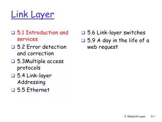
Data Link Layer • So far, sending signals over transmission medium. Suppose I can send data, then what? • Data link layer: responsible for error-free (reliable) communication between adjacent nodes. • Functions: framing, error control, flow control, addressing (in multipoint medium). University of Delaware CPEG 419
Flow Control • What is it? • Ensures that transmitter does not overrun receiver: limited receiver buffer space. • Receiver buffers data to process before passing it up. • If no flow control, receiver buffers may fill up and data may get dropped. University of Delaware CPEG 419
Stop-and-Wait • Simplest form of flow control. • Transmitter sends frame and waits. • Receiver receives frame and sends ACK. • Transmitter gets ACK, sends other frame, and waits, until no more frames to send. • Good when few frames. • Problem: inefficient link utilization. • In the case of high data rates or long propagation delays. University of Delaware CPEG 419
Sliding Window 1 • Allows multiple frames to be in transit at the same time. • Receiver allocates buffer space for n frames. • Transmitter is allowed to send n (window size) frames without receiving ACK. • Frame sequence number: labels frames. University of Delaware CPEG 419
Sliding Window 2 • Receiver ack’s frame by including sequence number of next expected frame. • Cumulative ACK: ack’s multiple frames. • Example: if receiver receives frames 2,3, and 4, it sends an ACK with sequence number 5, which ack’s receipt of 2, 3, and 4. University of Delaware CPEG 419
Sliding Window 3 • Sender maintains sequence numbers it’s allowed to send; receiver maintains sequence number it can receive. These lists are sender and receiver windows. • Sequence numbers are bounded; if frame reserves k-bit field for sequence numbers, then they can range from 0 … 2k -1 and are modulo 2k. University of Delaware CPEG 419
Sliding Window 4 • Transmission window shrinks each time frame is sent, and grows each time an ACK is received. University of Delaware CPEG 419
Example: 3-bit sequence number and window size 7 A B 0 1 2 3 4 5 6 7 0 1 2 3 4... 0 1 2 3 4 5 6 7 0 1 2 3 4 0 1 2 0 1 2 3 4 5 6 7 0 1 2 3 4 0 1 2 3 4 5 6 7 0 1 2 3 4 RR3 0 1 2 3 4 5 6 7 0 1 2 3 4 0 1 2 3 4 5 6 7 0 1 2 3 4 3 0 1 2 3 4 5 6 7 0 1 2 3 4 4 5 0 1 2 3 4 5 6 7 0 1 2 3 4 RR4 6 0 1 2 3 4 5 6 7 0 1 2 3 4 0 1 2 3 4 5 6 7 0 1 2 3 4 University of Delaware CPEG 419
Sliding Window (cont’d) • RR n acknowledges up to frame n-1. • There is also RNR n, which ack’s up to frame n-1 but no longer accepts more frames. • RNR shuts down the receive window and consequently the transmission window. • Need subsequent RR to re-open window. University of Delaware CPEG 419
Piggybacking • When both endpoints transmit, each keeps 2 windows, transmitter and receiver windows. • Each send data and need to send ACKs. • When sending data, transmitter can “piggyback” the acknowledgment information. • When no data, send just the ACK. University of Delaware CPEG 419
Duplicate ACKs • When no data, must re-send last ACK. • Duplicate ACKs: report potential errors. University of Delaware CPEG 419
Error Detection • Transmission impairments lead to transmission errors: change of 1 or more bits in transmitted frame. • Transmission errors defined using probabilities: transmission medium modeled as a statistical system. University of Delaware CPEG 419
Error Probabilities 1 • Definitions: • Pb probability of single bit error (bit error rate); constant and independent for each bit. • P1 probability frame received with no errors. • P2 probability frame received with 1 or more undetected errors. • P3 probability frame received with 1 or more detected bit errors, but no undetected ones. University of Delaware CPEG 419
Error Probabilities 2 • If no error detection mechanism, P3 = 0. • P1 = (1 - Pb)F and P2 = (1- P1), where F is size of frame in bits. • P1 decreases as Pb increases. • P1 decreases as F increases. University of Delaware CPEG 419
Example • 64-kbps ISDN channel’s bit error rate is less than 10-6. User requirement of at most 1 frame with undetected bit error per day. Frame is 1000 bits. • In a day, 5.529 x 10⁶ frames transmitted. • Required frame error rate of 1/ 5.529 x 10⁶, or P2 = 0.18 x 10⁻⁶. • But Pb = 10-6, so P1 = (1-Pb)F = 0.999 and P2 = 1 - P1 = 10-3, which is >>> required P2 University of Delaware CPEG 419
Error Detection Schemes • Transmitter adds additional bits for error detection. • Transmitter computes error detection bits as function of original data. • Receiver performs same calculation and compares results. If mismatch, then error. • P3 probability error detection scheme detects error; P2 residual error rate or probability error goes undetected. University of Delaware CPEG 419
Parity • Simplest error detection scheme. • Append parity bit to data block. • Example: ASCII transmission • 1 parity bit appended to each 7-bit ASCII character. • Even parity: 8-bit code has even number of 1’s. • Odd parity: 8-bit code has odd number of 1’s. University of Delaware CPEG 419
Parity Check • Example: transmitting ASCII “G” (1110001) using odd parity. • Code transmitted is 11100011. • Receiver checks received code and if odd number of 1’s, assumes no error. • Suppose it receives 11000011, then detects error. • NOTE: If more than 2 bits in error, may not be detected. University of Delaware CPEG 419
Cyclic Redundancy Check • CRC is one of the most effective and common error detecting schemes. • Let M be m-bit message, G (r+1)-bit pattern. • Transmitter appends r 0’s to M, 2r*M. • Divide 2r*M by G and add remainder to 2r*M forming T (m+r bits), which is transmitted. • Receiver computes T/G; if remainder, then error. University of Delaware CPEG 419
CRC Example • Frame M 1010001101 = x9+x7+x3+x2+x0. • Pattern G 110101. • Dividing (frame*25) by pattern results in 01110. • Thus T 101000110101110. • Receiver can detect errors unless received message Tr is divisible by G. University of Delaware CPEG 419
CRC • Patterns are expressed as polynomials G(x). • Example: • CRC-16 = x16+x15+x2+1 • CRC-CCITT = X16+x12+x5+1 University of Delaware CPEG 419