Download
1 / 99
1.22k likes | 2.48k Views
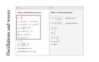
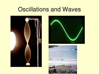
Oscillations and Waves. Wave Characteristics. Waves. A wave is a means of transferring energy and momentum from one point to another without there being any transfer of matter between the two points.

E N D
Oscillations and Waves Wave Characteristics
Waves A wave is a means of transferring energy and momentum from one point to another without there being any transfer of matter between the two points.
This illustrates that there is no net transfer of the medium through which the wave travels, only energy moves from place to place. In many examples, the wave carrying medium will oscillate with simple harmonic motion (i.e. a -x).
Duck oscillation Wave direction Progressive Waves Any wave that moves through or across a medium (e.g. water or even a vacuum) carrying energy away from its source is a progressive (travelling) wave. E.g.A duck on water: As the wave passes the duck, the water (and duck) only oscillate vertically.
Describing Waves 1. Mechanical or Electromagnetic Mechanical waves are made up of particles vibrating. e.g. sound – air molecules; water – water molecules All these waves require a substance for transmission and so none of them can travel through a vacuum. Electromagnetic waves are made up of oscillating electric and magnetic fields. e.g. light and radio These waves do not require a substance for transmission and so all of them can travel through a vacuum.
Describing Waves 2. Progressive or Stationary Progressive waves are waves where there is a net transfer of energy and momentum from one point to another. e.g. sound produced by a person speaking; light from a lamp Stationary waves are waves where there is a NO net transfer of energy and momentum from one point to another. e.g. the wave on a guitar string
vibrations wave direction LONGITUDINAL WAVE Describing Waves 3. Longitudinal or Transverse Longitudinal waves are waves where the direction of vibration of the particles is parallel to the direction in which the wave travels. e.g. sound
vibrations wave direction TRANSVERSE WAVE Describing Waves Transverse waves are waves where the direction of vibration of the particles or fields is perpendicular to the direction in which the wave travels. e.g. water and all electromagnetic waves Test for a transverse wave: Only TRANVERSE waves undergo polarisation.
Polarisation The oscillations within a transverse wave and the direction of travel of the wave define a plane. If the wave only occupies one plane the wave is said to be plane polarised.
Polarisation Light from a lamp is unpolarised. However, with a polarising filter it can be plane polarised.
Polarisation If two ‘crossed’ filters are used then no light will be transmitted.
Aerial alignment Radio waves (and microwaves) are transmitted as plane polarised waves. In the case of satellite television, two separate channels can be transmitted on the same frequency but with horizontal and vertical planes of polarisation. In order to receive these transmissions the aerial has to be aligned with the plane occupied by the electric field component of the electromagnetic wave. The picture shows an aerial aligned to receive horizontally polarised waves.
amplitude a undisturbed or equilibrium position Measuring waves Displacement, x This is the distance of an oscillating particle from its undisturbed or equilibrium position. Amplitude, a This is the maximum displacement of an oscillating particle from its equilibrium position. It is equal to the height of a peak or the depth of a trough.
Measuring waves Phase, φ This is the point that a particle is at within an oscillation. Examples: ‘top of peak’, ‘bottom of trough’ Phase is sometimes expressed in terms of an angle up to 360°. If the top of a peak is 0° then the bottom of a trough will be 180°.
Measuring waves Phase difference, Δφ This is the fraction of a cycle between two particles within one or two waves. Example: the top of a peak has a phase difference of half of one cycle compared with the bottom of a trough. Phase difference is often expressed as an angle difference. So in the above case the phase difference is 180°. Also with phase difference, angles are usually measured in radians. Where: 360° = 2π radian; 180° = π rad; 90° = π/2 rad
wavelength λ Measuring waves Wavelength, λ This is the distance between two consecutive particles at the same phase. Example: top-of-a-peak to the next top-of-a-peak unit – metre, m
Measuring waves Period, T This is equal to the time taken for one complete oscillation in of a particle in a wave. unit – second, s Frequency, f This is equal to the number of complete oscillations in one second performed by a particle in a wave. unit – hertz, Hz NOTE: f = 1 / T
The wave equation For all waves: speed = frequency x wavelength c = f λ where speed is in ms-1 provided frequency is in hertz and wavelength in metres
Each bright line in this diagram represents a crest and can be regarded as a WAVEFRONT.
A RAY can be thought of as a locus of one point on a wavefront showing the direction in which energy is travelling.
Download from http://phet.colorado.edu/simulations/index.php?cat=Sound_and_Waves
In the late 19th century physicists had been working extensively with electricity and magnetic fields. A great many discoveries in these fields were being made. At the same time it became universally accepted that the best model for light was the wave model. James Clerk Maxwell summarised, synthesised and unified these ideas. He came up with the idea that all of these phenomena, including light, were simply different forms of ELECTROMAGNETIC RADIATION
Electromagnetic waves are created by accelerating charges which result in a rapidly changing magnetic field and electric field travelling at right angles to each other and to their direction of travel. EM Wave applet: http://micro.magnet.fsu.edu/primer/java/scienceopticsu/electromagnetic/index.html
Although the previous image showed only two transverse waves, EM waves don’t look like these in reality. There are actually many planes of electric-magnetic field oscillations. Source: http://sol.sci.uop.edu/~jfalward/physics17/chapter11/chapter11.html
It is the FREQUENCY of the waves that determines the type of electromagnetic wave and the different frequencies make up the ELECTROMAGNETIC SPECTRUM Source: http://outreach.atnf.csiro.au/education/senior/astrophysics/images/em_spectrumextended.jpg
Note that VISIBLE LIGHT only makes up a small part of the spectrum Source: http://imgs.xkcd.com/comics/electromagnetic_spectrum_small.png
All electromagnetic waves travel with the same speed in free space. It is worthwhile to recall the orders of magnitude of the wavelengths of the principal radiations in the electromagnetic spectrum, such as the following
Wave Pulses • A pulse wave is a sudden distortion or disturbance that travels through a material or medium
Reflection of Pulses String with a fixed end • If a pulse travels along a string that is fixed to a rigid support, the pulse is reflected with a phase change of 180º • The shape of the pulse stays the same, except that it is inverted and travelling in the opposite direction • The amplitude of the pulse is slightly less as some energy is absorbed at the fixed end • When the (upward) pulse reaches the fixed end, it exerts an upward force on the support, the support then exerts and equal and opposite downward force on the string (reaction force), causing the inverted pulse to travel back along the string • http://rt210.sl.psu.edu/phys_anim/waves/indexer_waves.html
Reflection of Pulses String with a free end • If a pulse travels along a string that is tethered to a pole but free to move, the pulse is reflected with no phase change • The shape of the pulse stays the same, except that it is travelling in the opposite direction
Superposition Superposition is seen when two waves of the same type cross. It is defined as “the vector sum of the two displacements of each wave”:
reinforcement cancellation Superposition of waves This is the process that occurs when two waves of the same type meet. The principle of superposition When two waves meet, the total displacement at a point is equal to the sum of the individual displacements at that point
Law of Superposition (interference) Whenever two waves of the same type meet at the same point, the total amplitude (displacement) at that point equals the sum of the amplitudes (displacements) of the individual waves. (You tube link1 and link2)
For constructive interference at any point, wavefronts must be ‘in phase’ and their path difference must be a whole number of wavelengths: path difference = nλ For destructive interference at any point, wavefronts are ‘π out of phase’ and their path difference is given by: path difference = (n + ½) λ
Destructive interference i.e. dark or quiet. Waves are π rads out of phase. Constructive interference i.e. Loud or bright. Waves are in phase
Path Difference 2nd subsidiary maximum Q 1st subsidiary maximum P S1 Central maximum O S2 1st subsidiary maximum P’ 2nd subsidiary maximum Q’ At O : Zero path difference At P and P’ path difference = 1λ At Q and Q’ Path difference = 2λ
So in the above example… S2Q – S1Q = 2λ For constructive interference at any point, wavefronts must be ‘in phase’ and their path difference must be a whole number of wavelengths: path difference = nλ For destructive interference at any point, wavefronts are ‘π out of phase’ and their path difference is given by: path difference = (n + ½) λ
Task: On your interference diagram… • Draw in lines of constructive and destructiveinterference • Indicate the lines that join points… • a. in phase • b. 2π out of phase (path difference = λ) • c. 4π out of phase (path difference = 2λ) • d. 3π out of phase (path difference = 1.5λ)
Coherent waves A stable pattern of interference is only obtained if the two wave sources are coherent. Two coherent wave sources… i. have a constant phase difference, ii. thus produce waves with equal frequency.
Interference Interference occurs when two waves of the same type (e.g. both water, sound, light, microwaves etc.) occupy the same space. Wave superposition results in the formation of an interference pattern made up of regions of reinforcement and cancellation.
Thomas Young 1773 - 1829 Double slit interference with light This was first demonstrated by Thomas Young in 1801. The fact that light showed interference effects supported the theory that light was a wave-like radiation.
Experimental details Light source: This needs to be monochromatic (one colour or frequency). This can be achieved by using a colour filter with a white light. Alternatives include using monochromatic light sources such as a sodium lamp or a laser. Single slit: Used to obtain a coherent light source. This is not needed if a laser is used. Double slits: Typical width 0.1mm; typical separation 0.5mm. Double slit to fringe distance: With a screen typically 1.0m. The distance can be shorter if a microscope is used to observe the fringes.