Download
1 / 8
261 likes | 1.44k Views
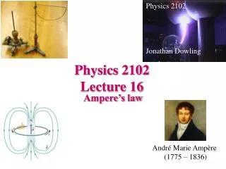
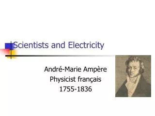
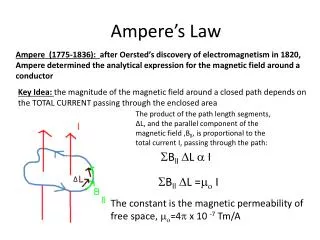
Ampere (1775-1836): after Oersted’s discovery of electromagnetism in 1820, Ampere determined the analytical expression for the magnetic field around a conductor. Ampere’s Law.

E N D
Ampere (1775-1836): after Oersted’s discovery of electromagnetism in 1820, Ampere determined the analytical expression for the magnetic field around a conductor Ampere’s Law Key Idea: the magnitude of the magnetic field around a closed path depends on the TOTAL CURRENT passing through the enclosed area The product of the path length segments, ∆L, and the parallel component of the magnetic field ,Bll, is proportional to the total current I, passing through the path: Bll L I ∆ Bll L = I The constant is the magnetic permeability of free space, =4 x 10 -7 Tm/A
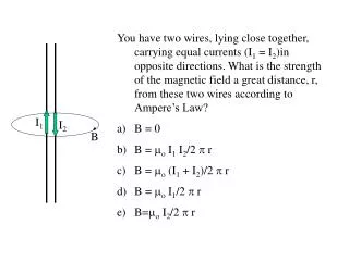
Magnetic Field around a Long, Straight, Conductor: At a given radius (r) from the conductor the magnetic field is constant : Bll= B r Applying Ampere’s Law: B L = I B is constant so we can take it outside of the sum! I BL = I The sum of all the path length segments is the circumference of the circle! B(2 r) = I B = I 2 r
Example: What is the magnetic field strength 15.0 cm away from a long straight conductor carrying a current of 10.0 Ampere? Ans: 1.33 x 10⁻⁵ T Force Between Two Parallel Conductors v Question 1: Two parallel conductors are side by side and carrying similar currents. The magnetic fields will cause: a) an attractive force on the wires b) repulsive force on the wires c) no force on the wires I v I
Question 2: Two parallel conductors are side by side and carrying opposite currents. The magnetic fields will cause: a) an attractive force on the wires b) repulsive force on the wires c) no force on the wires v I v I
Finding the magnetic force per unit length on the two parallel conductors: v L1 The magnitude of the magnetic field at a distance, d, from each conductor is: I1 v I2 B1 = I1 2 d and B2 = I2 2 d d The force of B1 on wire 2 is: L2 1 F1on2=I2L2B1sin F1on2 2 1 F1on2=I2L2B1 X X F1on2=I2L2 I1 2 d Direction is left B1
Similarly the force of B2 on 1 is: F2on1=I2L I1 2 d Direction is right! The force per unit length is F/L: F=I2 I1 L 2 d Units are N/m! Example 2: What is the force between two parallel conductors 20.0 cm long, each carrying a current of 15.0 Ampere if they are 5.0 cm apart? Ans: 1.8 x 10⁻⁴ N
Magnetic Field Strength at the centre of a Solenoid: X Y Consider a solenoid with length L and N turns each carrying a current I X L B=0 Field inside is uniform! X Field outside is zero! X Applying Ampere’s Law around the path WXYZ: Z Bll L = I W B Bll (WX) + Bll (XY) +Bll (YZ)+ Bll (ZW) = NI BL + 0 + 0+ 0 = NI B =NI L
Example 3: What is the magnetic field strength in the core of a solenoid 5.0 cm long with 300 turns carrying a current of 10.0 Ampere? Ans: 7.5 x 10 -2 T Assignment: Day 12- Section 8.4 P1-12, S1-4,6,10