Download

1 / 20
260 likes | 502 Views
Use Case, Component and Deployment Diagrams. University of Sunderland. Resources. UML in a Nutshell Object Oriented Software Engineering Eriksson, et al., 2004, UML 2 Toolkit, OMG Press. Use Case Modeling. An iterative process involving the customer. Invented by Ivar Jacobson

E N D
Use Case, Component and Deployment Diagrams University of Sunderland
Resources • UML in a Nutshell • Object Oriented Software Engineering • Eriksson, et al., 2004, UML 2 Toolkit, OMG Press.
Use Case Modeling • An iterative process involving the customer. • Invented by Ivar Jacobson • Describes what the system does to benefit users. • Clarifies and documents the key system needs. • Involves use cases, actors, and the system modeled (the ‘subject’), which is treated as a black box.
Purposes of Use Cases • To decide and describe the functional requirements. • To give a clear and consistent description of what the system should do. • To provide the basis for defining system tests. • To provide the ability to trace functional requirements to the system design.
The Process of Use-Case Modeling • Define the system • Find the actors and the use cases • Describe the use cases textually • Define the relationships between use cases and the actors • Validate the model
Who Cares? • Stakeholders • Developers • Project managers • Test teams • Marketing • Sales • Support • Documentation writers
Use-Case Validation • You must present the use cases to customers and end-users and discuss them. • They validate the model, indicating that the system correctly meets their expectations.
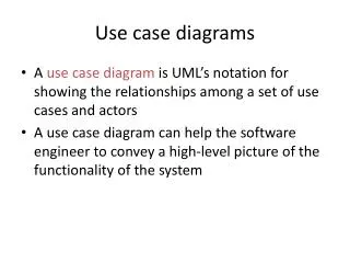
Use Case Diagram Notation • Represents the user view of the system. • Relates • Actors, and • Use cases • Only drawn if the customer demands them and then often not maintained. Usually replaced by a short written list, or by a functional requirements document. • Should be developed as part of the requirements definition process, not separately. Written documentation is mandatory. • Used to define the system test cases.
Sample Use Case Diagram Use Case Actor System
Actors • Represent users of a system or interfacing systems. Can be generalized (using ). • Interfacing systems can be diagrammed instead as a rectangle containing <<actor>> followed by the system name <<actor>> External System
Use Cases • Represent functionality or services provided by a system • Always initiated by an actor via an association. • Provides value to an actor via an association. • Has to be complete.
Use-Case Analysis • Just one way to follow the unified process. • You do this after you’ve done domain analysis and know what your major use cases are. Allows you to: • Refine your business classes and entities • Add additional classes • Add operations and attributes to those classes • You translate each use case into top-level sequence and activity diagrams • The classes in those diagrams represent entities, handle boundaries, and provide control. (One control class per use case at a coarse-grained level.)
Component Diagram Notation • Describe the organization and dependencies of the software components. This information is conceptually similar to that in a makefile. • Very rarely drawn since other notations are older and more suitable. • Most organizations use GANTT and PERT charts with written documentation.
Sample Component Diagram Component Interface Dependency
Component • Development-time or run-time physical object implementing the system.
Interface • A formally specified and documented boundary between two components.
Dependency • The components pointed to depend on the physical objects pointed from.
Deployment Diagram Notation • Shows the hardware configuration items and the mapping of software configuration items onto them. • Very rarely drawn as other notations are older and more suitable. • Most organizations document these relationships in a product specification. (This is mandatory for systems being developed for government or major companies.)
Sample Deployment Diagram Connection to some other hardware Hardware Node Software Component
General Rules for UML Diagrams • These diagrams are intended to present your system visually, so don’t go overboard with them. • A given diagram should have no more than 15 distinct meaningful elements. Anything more produces MEGO (“my eyes glaze over”) and creates opportunities for errors to creep in. • Go into detail only where it is needed. An analyst’s ability to work at an appropriate level of detail is valued by management.