Download
1 / 198
1.98k likes | 2.13k Views
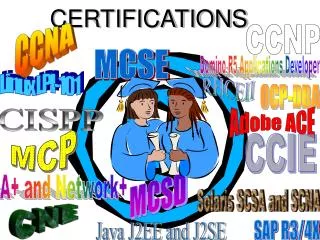
Communications and Services Certifications. CCNA. CCNA Exam. Exam Number - 640-801 Total Marks - 1000 Duration – 90 Mts Passing score – 849 Questions -45-55 Multiple Choice Simulations Drag and Drop. Benefits. Peer Validation Personal Potential Employer Career advancement.

E N D
CCNA Exam • Exam Number - 640-801 • Total Marks - 1000 • Duration – 90 Mts • Passing score – 849 • Questions -45-55 • Multiple Choice • Simulations • Drag and Drop
Benefits • Peer Validation • Personal • Potential Employer • Career advancement
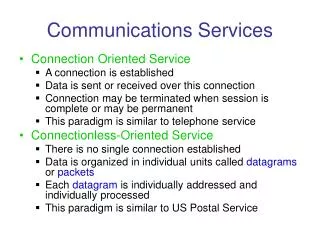
Data Networks • Sharing data through the use of floppy disks is not an efficient or cost-effective manner. • Businesses needed a solution that would successfully address the following three problems: • How to avoid duplication of equipment and resources • How to communicate efficiently • How to set up and manage a network • Businesses realized that networking technology could increase productivity while saving money.
Networking Devices • Equipment that connects directly to a network segment is referred to as a device. • These devices are broken up into two classifications. • End-user devices • Network devices • End-user devices include computers, printers, scanners, and other devices that provide services directly to the user. • Network devices include all the devices that connect the end-user devices together to allow them to communicate.
Network Interface Card A network interface card (NIC) is a printed circuit board that provides network communication capabilities to and from a personal computer. Also called a LAN adapter.
Hub Connects a group of Hosts
Switch Switches add more intelligence to data transfer management.
Router • Routers are used to connect networks together • Route packets of data from one network to another • Cisco became the de facto standard of routers because of their high-quality router products • Routers, by default, break up a broadcast domain
Network Topologies Network topology defines the structure of the network. One part of the topology definition is the physical topology, which is the actual layout of the wire or media. The other part is the logical topology,which defines how the media is accessed by the hosts for sending data. When you are cabling up your computers and networking devices, various types of topologies can be used. A topology defines how the devices are connected.
Bus Topology • A bus topology uses a single backbone cable that is terminated at both ends. • All the hosts connect directly to this backbone.
Ring Topology • A ring topology connects one host to the next and the last host to the first. • This creates a physical ring of cable.
Star Topology • A star topology connects all cables to a central point of concentration.
Extended Star Topology • An extended star topology links individual stars together by connecting the hubs and/or switches.This topology can extend the scope and coverage of the network.
Mesh Topology • A mesh topology is implemented to provide as much protection as possible from interruption of service. • Each host has its own connections to all other hosts. • Although the Internet has multiple paths to any one location, it does not adopt the full mesh topology.
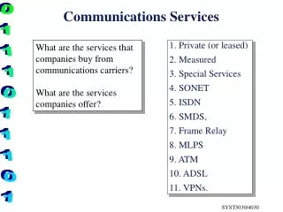
LANs, MANs, & WANs • One early solution was the creation of local-area network (LAN) standards which provided an open set of guidelines for creating network hardware and software, making equipment from different companies compatible. • What was needed was a way for information to move efficiently and quickly, not only within a company, but also from one business to another. • The solution was the creation of metropolitan-area networks (MANs) and wide-area networks (WANs).
Virtual Private Network A VPN is a private network that is constructed within a public network infrastructure such as the global Internet. Using VPN, a telecommuter can access the network of the company headquarters through the Internet by building a secure tunnel between the telecommuter’s PC and a VPN router in the headquarters.
What Are The Components Of A Network ? Mobile Users Home Office Internet Branch Office Main Office
Network Structure & Hierarchy Core Layer Distribution Layer Access Layer
Institute of Electrical and Electronics Engineers (IEEE) 802 Standards • IEEE 802.1: Standards related to network management. • IEEE 802.2: General standard for the data link layer in the OSI Reference Model. The IEEE divides this layer into two sublayers -- the logical link control (LLC) layer and the media access control (MAC) layer. • IEEE 802.3: Defines the MAC layer for bus networks that use CSMA/CD. This is the basis of the Ethernet standard. • IEEE 802.4: Defines the MAC layer for bus networks that use a token-passing mechanism (token bus networks). • IEEE 802.5: Defines the MAC layer for token-ring networks. • IEEE 802.6: Standard for Metropolitan Area Networks (MANs)
Why do we need the OSI Model? • To address the problem of networks increasing in size and in number, the International Organization for Standardization (ISO) researched many network schemes and recognized that there was a need to create a network model • This would help network builders implement networks that could communicate and work together • ISO therefore, released the OSI reference model in 1984.
Don’t Get Confused. ISO - International Organization for Standardization OSI - Open System Interconnection IOS - Internetwork Operating System To avoid confusion, some people say “International Standard Organization.”
The OSI Reference Model 7 Application The OSI Model will be used throughout your entire networking career! 6 Presentation 5 Session 4 Transport 3 Network Memorize it! 2 Data Link 1 Physical
Application Application (Upper) Layers Presentation Session OSI Model Transport Network Data Flow Layers Data-Link Physical
This layer deal with networking applications. Examples: Email Web browsers PDU - User Data Layer 7 - The Application Layer 7 Application 6 Presentation 5 Session 4 Transport 3 Network 2 Data Link 1 Physical Each of the layers have Protocol Data Unit (PDU)
This layer is responsible for presenting the data in the required format which may include: • Code Formatting • Encryption • Compression • PDU - Formatted Data Layer 6 - The Presentation Layer 7 Application 6 Presentation 5 Session 4 Transport 3 Network 2 Data Link 1 Physical
This layer establishes, manages, and terminates sessions between two communicating hosts. • Creates Virtual Circuit • Coordinates communication between systems • Organize their communication by offering three different modes • Simplex • Half Duplex • Full Duplex • Example: • Client Software • ( Used for logging in) • PDU - Formatted Data Layer 5 - The Session Layer 7 Application 6 Presentation 5 Session 4 Transport 3 Network 2 Data Link 1 Physical
Half Duplex • It uses only one wire pair with a digital signal running in both directions on the wire. • It also uses the CSMA/CD protocol to help prevent collisions and to permit retransmitting if a collision does occur. • If a hub is attached to a switch, it must operate in half-duplex mode because the end stations must be able to detect collisions. • Half-duplex Ethernet—typically 10BaseT—is only about 30 to 40 percent efficient because a large 10BaseT network will usually only give you 3 to 4Mbps—at most.
Full Duplex In a network that uses twisted-pair cabling, one pair is used to carry the transmitted signal from one node to the other node. A separate pair is used for the return or received signal. It is possible for signals to pass through both pairs simultaneously. The capability of communication in both directions at once is known as full duplex.
This layer breaks up the data from the sending host and then reassembles it in the receiver. • It also is used to insure reliable data transport across the network. • Can be reliable or unreliable • Sequencing • Acknowledgment • Retransmission • Flow Control • PDU - Segments Layer 4 - The Transport Layer 7 Application 6 Presentation 5 Session 4 Transport 3 Network 2 Data Link 1 Physical
Sometimes referred to as the “Cisco Layer”. • End to End Delivery • Provide logical addressing that routers use for path determination • Segments are encapsulated • Internetwork Communication • Packet forwarding • Packet Filtering • Makes “Best Path Determination” • Fragmentation • PDU – Packets – IP/IPX Layer 3 - The Network Layer 7 Application 6 Presentation 5 Session 4 Transport 3 Network 2 Data Link 1 Physical
Performs Physical Addressing • This layer provides reliable transit of data across a physical link. • Combines bits into bytes and bytes into frames • Access to media using MAC address • Error detection, not correction • LLC and MAC • Logical Link Control performs Link establishment • MAC Performs Access method • PDU - Frames Layer 2 - The Data Link Layer 7 Application 6 Presentation 5 Session 4 Transport 3 Network 2 Data Link 1 Physical
This is the physical media through which the data, represented as electronic signals, is sent from the source host to the destination host. • Move bits between devices • Encoding • PDU - Bits Layer 1 - The Physical Layer 7 Application 6 Presentation 5 Session 4 Transport 3 Network 2 Data Link 1 Physical
FCS FCS Data Encapsulation Application Presentation PDU Session Upper-Layer Data Transport Segment TCP Header Upper-Layer Data Network Packet IP Header Data LLC Header Data Data-Link Frame MAC Header Data Physical Bits 0101110101001000010
OSI Model Analogy Application Layer - Source Host After riding your new bicycle a few times in Bangalore, you decide that you want to give it to a friend who lives in DADAR, Mumbai.
OSI Model Analogy Presentation Layer - Source Host Make sure you have the proper directions to disassemble and reassemble the bicycle.
OSI Model Analogy Session Layer - Source Host Call your friend and make sure you have his correct address.
OSI Model Analogy Transport Layer - Source Host Disassemble the bicycle and put different pieces in different boxes. The boxes are labeled “1 of 3”, “2 of 3”, and “3 of 3”.
OSI Model Analogy Network Layer - Source Host Put your friend's complete mailing address (and yours) on each box.Since the packages are too big for your mailbox (and since you don’t have enough stamps) you determine that you need to go to the post office.