Download
1 / 35
390 likes | 794 Views
Chapter 8 Optical fiber splicing. Attenuation curve for silica optical fiber. Loss measurements in optical fiber networks - at splices between fibers with mode fields of different sizes - can give unexpected values.

E N D
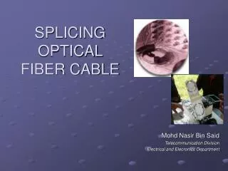
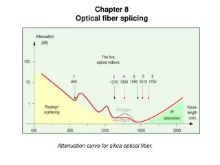
Chapter 8 Optical fiber splicing Attenuation curve for silica optical fiber.
Loss measurements in optical fiber networks - at splices between fibers with mode fields of different sizes - can give unexpected values.
Losses occur when the transmitting fiber has a larger NA than the receiving fiber.
When fibers with different core diameters are spliced losses will occur and the mode field diameter of the lightpulse will change.
Differences in core diameter have a greater effect on a mechanical splice than on a fusion splice.
Non-circularity of the core can affect the loss values for a splice. For connectors without guiding slots, this can mean different loss values after each disconnection/reconnection.
Graph of loss through a connector with radial misalignment between the two fibers.
Graph of loss caused by angular deviation between meeting fiber ends.
The end surfaces of the PC connector’s ferrules are ground to a hemispherical shape.
If the mating parts of a PC connector are ground unevenly, an air gap may form between them. This air gap markedly reduces transmission for SM fiber when laser is used.
A poorly finished end surface results in increased splice loss.
The quality of the fiber cutter used can often determine the performance of a splice. A fiber cutter of high quality cuts the fiber rapidly and safely at a 90° angle, without deforming the cutting surface. The cutters above are from Sumitomo (left) and Ericsson (right). The Sumitomo cutter also cuts fiber ribbon.
Simplified illustration of the most important steps in fusion splicing.
Two electronically scanned images. The picture to the left shows a picture taken during the fusion process of a single fiber and the picture to the right shows the same for a 12-fiber ribbon splicer. The fiber core is visible as a light-colored stripe in the middle of the fiber (left picture only). This picture shows also the fiber in both horizontal and vertical direction. The picture with the 12-fiber ribbon is only in vertical direction
The alignment in a fusion splicer for fiber ribbon uses V-groves for x and y direction
The loss in a fusion splice can be affected by various parameters, such as cutting angle, poor alignment, or core/cladding concentricity.
The fibers are pushed from either end into a precision-drilled tube.
A three-rod splice is quickly and easily made; it is often used in cable or fiber performance measurements.
Three mechanical splices,to the left is the three rod splice, in the middle the Fiberlock® (3M) and to the right is the Fingersplice® (AMP).
A method of mechanical splicing of up to 12 fiber ribbons in a splicing matrix
Two splices with cylindrical, face-ground ferrule mounted in a bushing.
LME connector, one of the first connectors for optical fiber cable. The SMA connector became an international standard. The figure shows one connector with ceramical ferrule and one with a metallic ferrule.
FC–FC/PC connector in bits and pieces. To the left is the mounting bushing to be fitted in the ODF box .
The PC connector’s ferrule is ground with a spherical curvature. The ferrule shown to the left has been ground according to the super PC method, and the ferrule to the right according to the ultra PC method.
SC connector for analog transmissions, the ferrule is polished with 8 degree angle. These connectors are generally in green. SC connector for standard applications.
The SC con-nector has high packing density thanks to its rectangular shape and snap-in closure. The ST connector with bayonet coupling and pure ceramic ferrule.
Connector for FDDI network. The connector contains termination for fiber in and fiber out. Schematic diagram of a biconical splice. Biconical connector
Expanded beam splice. Usually, several fibers are terminated in a single splice.
Military field connector utilizing the expanded beam concept.
Light coming out of a 12- fiber MT connector Comparision between the 12- fiber MT-connector representing the ribbon technology an twelve SC-connectors representing the single fiber technology MT-connector for 4-, 8- and 12 fiber ribbon, note the guidening pin in middle connector.