Download
1 / 24
240 likes | 451 Views
Automatic Control of Wheeled Mobile Robots. Subhasis Behera Guided by – Mr. Raman Bedi Department of Mechanical Engineering NIT Jalandhar. The Objective. Studying various feedback control strategies used to control WMRs.

E N D
Automatic Controlof Wheeled Mobile Robots Subhasis Behera Guided by – Mr. Raman Bedi Department of Mechanical Engineering NIT Jalandhar
The Objective • Studying various feedback control strategies used to control WMRs. • Kinematic modeling of a car like WMR according to the constraints of geometry of the vehicle and nonslip motion. • Design and construction of a 3 wheeled car like WMR.
The Objective • Implementing the control strategy in the kinematic model and then controlling the vehicle. • Devising an algorithm to convert the control parameters into the signals to control the motors. • Designing and making the control circuit for controlling the stepper motors from the signals generated by the parallel port.
Basic Control System Low level program to convert the parameters into sequence signals to the driver circuit. Mathematical Model/ Control Strategy (v,δ) Sub-program to translate model's result into controllable parameters (v_F, v_Rl, v_Rr) Computer Program Parallel port Driver Circuit/ Power Supply Rr Vehicle F Rl
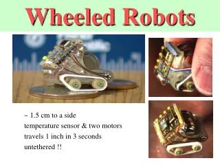
The Vehicle • The WMR is a car like vehicle, driven by the 2 rear wheels and a front wheel steers the vehicle. • The kinematic constraints of the vehicle geometry gives the required values of the various control parameters. • These control parameters are then modified so as to change them to the appropriate values achievable by the physical system.
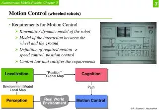
Kinematics Kinematics can be divided into the following two categories: • Control strategy • Mathematical model The Control strategy is an algorithm which generates the velocity and steering wheel orientation for the WMR, based on its current posture in the GPS. Mathematical model or the kinematic model is a mathematical representation of the actual vehicle. The kinematic model gives the values of the actual vehicle speeds at the various wheels when the vehicle is following a particular pattern of motion outlined by the control strategy.
e2 e3 e1 q2 P(q1,q2,q3) q1 Kinematics δ
Control Strategy The control strategy being used in the model is: v= v0+vpar*e1 δ = cpar*e3 where, e1 = (xd-q1)*cos(q3)+(yd-q2)*sin(q3) e2 = -(xd-q1)*sin(q3)+(yd-q2)*cos(q3) e3 = atan((yd-q2)/(xd-q1))-q3 e1, e2 and e3 are the local longitudinal, lateral and angular co-ordinate values respectively. vpar, cpar are proportionality constants.
Kinematic model Once we get the values of v and δ from the strategy, they are converted to the actual values to be used as control parameters in the actual vehicle according to the following algorithm. v_Rl = v*(1-b/l*tanδ) v_Rl_a=(round(v_Rl*t/step_distance)*step_distance)/t v_Rr_a = v_Rl_a*(1+b/l*tanδ)/(1-b/l*tanδ) v_a = v_Rl_a/(1-b/l*tanδ) x=(l/tanδ)*sin((v_a/l)*tanδ*t) y=(l/tanδ)*(1-cos((v_a/l)*tanδ*t) q1=q1+x*cos(q3)-y*sin(q3); q2=q2+x*sin(q3)+y*cos(q3); q3=q3+((v_a/l)*tanδ*t);
Stepper Motor Control • The WMR is driven by 3 stepper motors – one for the steering wheel and one each for the rear wheels. • The control of stepper motor involves two aspects – an electronic driver circuit, and a sequence generator software. • The interfacing of the software with the driver circuit is done through the parallel port.
Stepper Motors Stepper motors are electric motors without commutators. All windings of the motor are part of the stator and the rotor is a permanent magnet. Energizing the different windings in sequence enable rotation of the shaft in discrete steps. Types of Stepper Motors: • Variable reluctance motors • Unipolar motors • Bipolar motors • Bifilar motors • Multiphase motors
Control Sequence: Winding 1a 1 1 0 0 1 1 0 0 Winding 1b 0 0 1 1 0 0 1 1 Winding 2a 0 1 1 0 0 1 1 0 Winding 2b 1 0 0 1 1 0 0 1 time ---> Stepper Motors • The WMR is driven by unipolar stepper motors having a resolution of 7.5°/step. Unipolar Stepper Motor
+12 Motor Windings Parallel port Stepper Motors Driving Ckt. Driving the stepper motors require an electronic device to switch the current in the windings in the desired sequence. ULN-2003
The Control Software • Platform – MS-DOS, Win98 • Programming Language – C++ • Port Interface – Parallel port
The Control Software • The Software consists of three components: • Stepper motor control functions – hardware level functions, includes the various algorithms for driving the stepper motors. • WMR specific functions – includes the kinematic model of the WMR. • Plotting functions – various plotting functions for displaying vehicle motion in real-time.
Program Structure plot.h stepper.h wmr.h main program • The software code is organised into a set of header files which correspond to the 3 sub-components.
Program Structure include<stepper.h> include<wmr.h> include<plot.h> main() { initializeMotors(); initializeGFX(); ---main motion loop--- calculating v, delta; moveVehivle(); ---------------------- closeGFX(); }
Stepper Motor Control Functions • With 4 bits for one motor, control of three motors require 12 bits. • The parallel port organizes data pins into two sets of 8 and 4 bits each, with port addresses 0x378 and 0x37A respectively. • Port 0x378 handles two motors(for the rear driving wheels) and port 0x37A handles the steering motor
WMR Motion Algorithm - moveVehicle() moveVehicle(delta, v, t, distance) calculate the delay between consecutive steps for each of the rear motors for a uniform stepping speed in the specified time interval setSteering() function call calculate the achievable values of v, v_Rl, v_Rr determine a step timing array for each motor consisting of the instants at which steps have to be taken calculate the values of q1, q2 and q3 combine the individual step timing arrays into a unified step timing array indicating the timings and the required motor to be stepped translate the values of v_Rl,v_Rr into the no. of steps to be taken in the specified time interval by the rear wheels execute the stepping sequence by calling the step() funcion at each instant of the unified timing array
Plotting Functions • Draws the co-ordinate system • Displays the position of WMR at any instant • Displaying information such as current co-ordinate (q1,q2,q3) and the status of WMR motion (i.e. steering or moving etc.).
Plotting Functions • As opposed to the WMR co-ordinate system, the screen co-ordinate system, i.e. the pixel positions start at the top-left corner of the screen and increase from left to right along the width and from top to bottom along the height. • Thus we need to map the WMR co-ordinate system into the screen co-ordinate system
q2 q2p q1 q2p Transformation Algorithm • q1p=q1*q1_SF+q1_offset • q2p=screen_h-(q2*q2_SF+q2_offset)