Download
1 / 17
170 likes | 298 Views
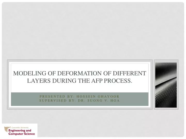
Modeling of deformation of different layers during the AFP process. Presented By: Hossein Ghayoor Supervised By: Dr. Suong V. Hoa. Introduction. Viscoelastic properties Different properties of each layer Effect of time and temperature

E N D
Modeling of deformation of different layers during the AFP process. Presented By: HosseinGhayoor Supervised By: Dr. Suong V. Hoa
Introduction • Viscoelastic properties • Different properties of each layer • Effect of time and temperature • Understanding of residual stress and final state of material after manufacturing
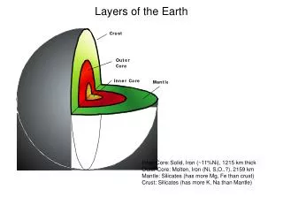
Introduction Different Temperature Different Properties Viscoelastic Problem Last Layer Layer 3 Layer 2 Layer 1 Mold Figure From: Analysis of Process-Induced Residual Stresses in Tape Placement, F. Sonmez, H. T. Hahn, M. Akbulut, J. of Thermoplastic Composite Materials, 2002
Viscoelastic Properties of Carbon-PEEK • Creep Properties of PEEK • Carbon fiber remains elastic Figure From: Characterization and modeling of nonlinear viscoelastic response of PEEK resin and PEEK composites, X.R. Xiao, C.C. Hiel, A.H. Cardon, Composite Engineering, 1994
Viscoelastic Properties of Carbon-PEEK The increase in number of unit cell columns (horizontal) Five by five block of unit cell minimizes the effect of boundary conditions The increase in number of unit cell rows (vertical)
Viscoelastic Properties of Carbon-PEEK Creep/ Relaxation Properties of Carbon-PEEK composite
Homogenized Properties of Carbon-PEEK C22 Figure From: A thermoviscoelastic analysis of process-induced internal stresses in thermoplastic matrix composites, SunderlandP., Yu W., Manson J., Polymer Composites, 2001
Viscoelastic Finite Element Formulation:
New Boundary Conditions Attaching the nodes in the stiffness matrix
Multi-Layer • Each 8-noded viscoelastic element can represent a unit cell (computational time is manytimes less) • Different Scenarios can be analyzed • Timing, thickness, temperature can be changed in the analysis
Typical Analysis Result two-step constant stress (one layer) One-step constant stress (one layer)
Typical Analysis Result One-step ramp stress (one layer) Maximum Strain Time(s)
Typical Analysis Result Strain in the first layer (ramp stress) Maximum Strain Depositing second layer Time(s)
Typical Analysis Result Strain in first layer (ramp stress) Maximum Strain fifth layer deposited fourth layer deposited third layer deposited Second layer deposited Time(s)
Conclusion • Residual Strain/Stress can be predicted and can be used in manufacturing design to optimize the design. • With developed modeling method different Scenarios of Manufacturing in terms of Timing, Thickness can be modeled and analyzed.