Download
1 / 8
130 likes | 1.36k Views
HIGH VOLTAGE DC UPTO 3KV FROM AC BY USING DIODE AND CAPACITORS IN LADDER NETWORK. Submitted by:. Project overview Block diagram Capacitor Diode Schematic & working of project Applications Advantages Future scope Conclusion . Contents .

E N D
HIGH VOLTAGE DC UPTO 3KV FROM AC BY USING DIODE AND CAPACITORS IN LADDER NETWORK Submitted by:
Project overview • Block diagram • Capacitor • Diode • Schematic & working of project • Applications • Advantages • Future scope • Conclusion Contents
This project describes the design and implementations from a single phase ac to high voltage DC power supply till 10kVoutput. • The implementation of the hardware work to build a high voltage DC power supply is meant for use in the laboratory. • The designed DC power supply can be used in industrial applications also. • The design of the circuit involves voltage doubler, whose principle is to double the output voltage. • The output from the voltage doubler is given to a series of cascaded circuit that generates up to 10KV but for the student project it is advisable to go up to 2KV for safety reasons. Project overview
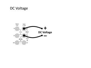
A basic capacitor has two parallel plates separated by an insulating material • A capacitor stores an electrical charge between the two plates • The unit of capacitance is Farads (F) Capacitor
Electrons on the left plate are attracted toward the positive terminal of the voltage source • This leaves an excess of positively charged holes • The electrons are pushed toward the right plate • Excess electrons leave a negative charge _ + - + Storing a charge between the plates
Simplest semiconductor device • Non linear • Used in power supplies • Voltage limiting circuits Diode
This project uses voltage multiplier circuit in multistage using a no of silicon diodes (D1-D8) and a set of electrolytic capacitors of 2 no’s of 100mf/400V connected in series. • Thus 16 capacitor of 100mf/400V are used for 8 stage voltage multiplication. • Thus if the input is 230v rms the output will be approximately [sqrt 2 x 230 x 8 = appx 2.5kv]. • In order to measure this voltage a potential divider arrangement comprising of 10resistors in series is made such that the voltage across 1 resistor is 2.5/10=250V, Which can be easily read by any standard meter to indicate that the full voltage is approximately 2.5kV. • 500k resistors are connected across each pair of capacitors to discharge them automatically after use, it will prevent from high voltage electric shock. Working of project