Download
1 / 61
610 likes | 631 Views
Learn about transmission errors, error detecting and error correcting codes, frame delimiters, acknowledgments, flow control, and examples of HDLC and PPP.

E N D
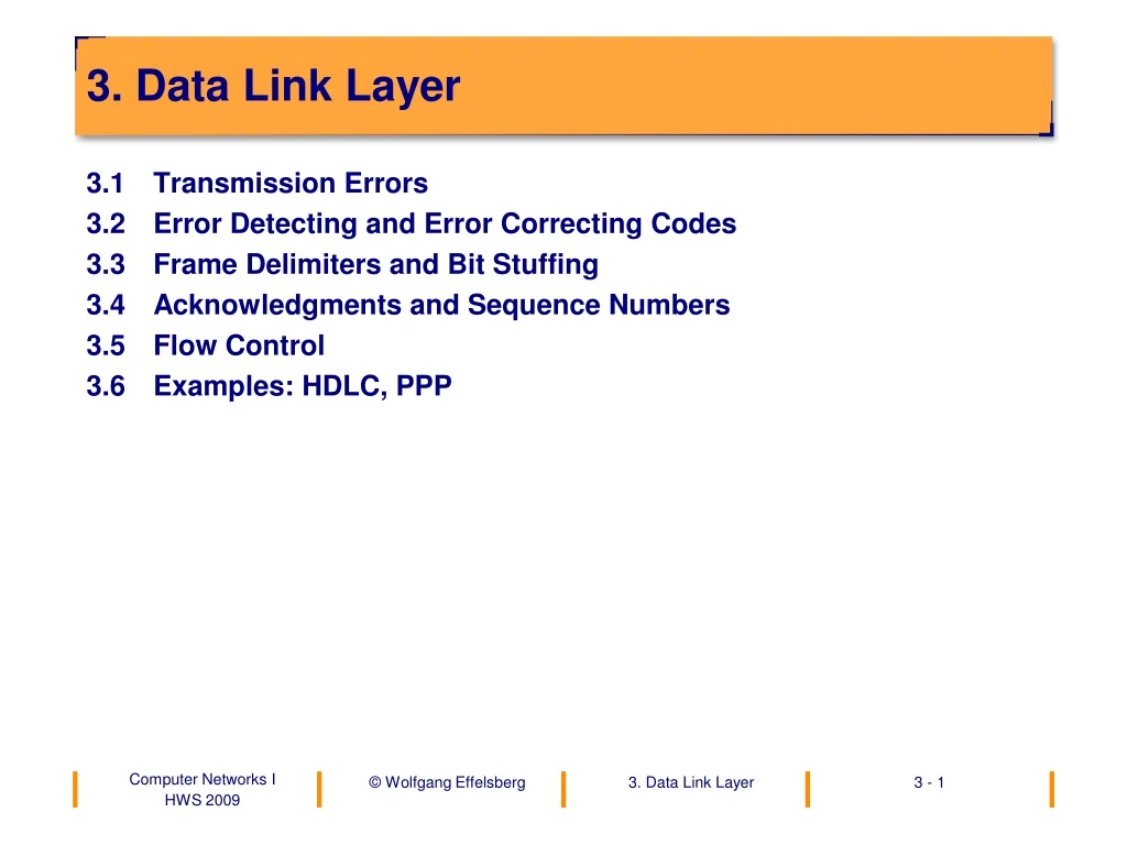
3. Data Link Layer • 3.1 Transmission Errors • 3.2 Error Detecting and Error Correcting Codes • 3.3 Frame Delimiters and Bit Stuffing • 3.4 Acknowledgments and Sequence Numbers • 3.5 Flow Control • 3.6 Examples: HDLC, PPP
Functions of the Data Link Layer (Layer 2) • Detection and correction of transmission errors between neighbors on the same physical link • Flow control • In LANs also: Medium Access Control (MAC)
802.1 802.2 LLC Data Link Layer MAC MAC MAC MAC 802.4 802.5 802.3 802.11WLAN Physical Layer Token Bus Token Ring CSMA/CD þ ý ü + physical media The Data Link Layer in LANs (IEEE 802) • As standardized by IEEE and ISO
3.1 TransmissionErrors • White noise • Signal distortion • Cross modulation on cables • Impulse noise • mostly caused by switching equipment • typically lasts approximately 10 ms (560 bits destroyed at 56 kbit/s!) • Often, errors occur in clusters. • Advantage: Only a few packets contain errors. • Disadvantage: Clustered errors are difficult to recognize and correct.
Probability of Transmission Errors • Example of an empirically determined error rate • Probability for a faulty packet for telephone lines and packets of n • bytes: p(n) = 10-4 n0.8 n p(n) 8 5.278031E-04 16 9.189586E-04 32 1.600000E-03 64 2.785761E-03 128 4.850293E-03 256 8.444851E-03 512 1.470334E-02 1024 0.0256
3.2 Error Detecting and Error Correcting Codes • Error: The data received is not identical to the data sent. • For error correction the user data must be supplemented by control infor-mation (redundancy). • The amount of redundancy determines the number of errors that can be detected or even corrected by the receiver. • The relationship between the amount and type of redundancy and its error detection and error correction potential is the topic of coding theory.
Bit 1011 Bit 2101 Bit 3 000 Bit 4010 Bit 5 0 00 Bit 6010 Bit 7 1 1 1 00 1 even Parity bit -------------------------------------------------------- Parity 1 1 0 odd A Simple Error Detection Mechanism: The Parity Bit
Properties of the Parity Bit • The parity bit supplements the number of ones contained in the user data field to an even or odd total number. • 1 0 0 1 1 1 0 0 0 • 1 0 1 1 1 1 0 0 1 • Information Parity bit(for evenparity) • Used in asynchronous transmission. And in many other places in computers. • Only a single bit error (or an odd number of bit errors) can be detected, and bit errors cannot be corrected.
Hamming Distance (1) • Hamming distance d between two code words • Number of bit positions in which two code words c1, c2differ. • Example: d(10001001, 10110001) = 3 • Can be computed as the number of bits of c1 XOR c2. • Hamming distance D of a complete code C
Hamming Distance (2) Theorem The ability of a code to detect errors and correct errors is a function of its Hamming distance. To detecte bit errors, a Hamming distance of e + 1 is necessary. To correct e bit errors, a Hamming distance of 2e + 1 is necessary.
How Much Redundancy Do We Need? • The code may consist of m character bits. How many check bits do we need in order to correct a 1 bit error? r? m n = m + r • There are 2mlegal character codes. • For every code word there must be n illegal code words around it with a distance of one bit. • 2nis the total number of code words we can form. • (n + 1) 2m 2n=> (m + r + 1) 2r • This gives the lower limit for r. • Example: • m = 7(8 + r) 2r=> r 4
Disadvantage of Error Correcting Codes • Large overhead (much redundancy). Exists in all transmissions, including the error-free ones. • Therefore: • Error detection and retransmission are more efficient in most classical computer network situations.
Examples • An Error-Detecting Code • A code with one parity bit (even or odd) per code word. • => Hamming distance D = 2 • => Recognition of a 1-bit error is possible • (in fact, all errors with an odd number of bits) • An Error-Correcting Code • Four code words: • 0000000000, 0000011111, 1111100000, 1111111111 • => Hamming distance D = 5 • => Correction of all 2-bit errors is possible • Example: 00000 00111 => 00000 11111 • 2-bit error nearest code word
Cyclic Redundancy Check (CRC) • Basic Idea • Consider the bit pattern as a representation of a polynomial with the co-efficients 0 and 1. Example: 11001 = x4 + x3 + x0 • Select a generator polynomial G(x) of degree g. • Add a checksum to the message M(x) in such a way that the polynomial T(x), formed by the message with attached checksum, is divisible by G(x). • Transmit T(x).
Algorithm CRC • We have G(x) of degree g and begin by attaching g 0-bits to the message, giving xgM(x). 1. Divide xgM(x) by G(x). Do the division modulo 2. 2. Subtract the remainder from xgM(x), modulo 2 3. The result is T(x), the message including the checksum, ready for transmission.
Example of the CRC Computation • Frame: 1101011011, Generator: 10011. Attach four 0-Bits: • 11010110110000 : 10011 = 1100001010 • 10011 • 10011 • 10011 • 00001 • 00000 • 00010 • 00000 • 00101 • 00000 • 01011 • 00000 • 10110 • 10011 • 01010 • 00000 • 10100 • 10011 • 01110 • 00000 • remainder: 1110 (division modulo 2: no carry when subtracting)
Generator Polynomials in International Standards • CRC-12 = x12 + x11 + x3 + x2 + x + 1 • Used for 6-bit character codes. • CRC-16 = x16 + x15 + x2 + 1 (ISO) • CRC-CCITT = x16 + x12 + x5 + 1 (CCITT) • Both used for 8-bit character codes. • Error recognition potential of CRC-16, CRC-CCITT (16 bits) • (results from coding theory): • all single and double bit errors • all errors with an odd number of bits • all bursterrors with a length ≤16 • 99.99 % of all longer bursterrors
Implementation of the CRC in Hardware • Implementation of the CRC • The CRC calculation can be implemented in hardware very efficiently (for example, on an HDLC chip) with a shift register and the bitwise XOR function.
3.3 Frame Delimiters and Bit Stuffing • For the use of error detecting and error correcting codes, the data stream must be partitioned into frames. • Problem: How can we delimit these frames in the physical layer bit stream if arbitrary bit patterns can occur in the user data? • Solution: Bit Stuffing • We choose 01111110 as the frame delimiter (“flag”). The sender always inserts a 0 after five 1’s in the user data stream before passing the data on to the framing function.
0 1 1 1 1 1 1 0 1 0 1 1 1 1 1 0 1 0 1 Transmitter Line 0 1 1 1 1 1 0 1 0 1 0 1 1 1 1 1 0 0 1 0 1 Receiver 0 1 1 1 1 1 1 0 1 0 1 1 1 1 1 0 1 0 1 Bit Stuffing Example If the receiver sees a 0 after five 1’s, it always removes it from the data stream before passing the data on to the user (higher layer).
0/0 0/0 A A 0/0 1/1 1/1 0/0 0/0 0/0 B B 1/1 0/0 1/1 0/0 0/0 C C 0/0 0/0 1/1 1/1 D D 0/0 1/1 1/1 E E 1/1 1/1 1/10 1/1 F F 0 1/1 G H Notation: e/o e = event o = output Bit Stuffing: Finite Automata • Finite automata for transmitter and receiver for a transmission with bit stuffing. Transmitter (event: bit to be transmitted) Receiver (event: arriving bit) Inserted 0-bit removed delimiter (error)
delimiter delimiter Flag Checksum (Frame Check Sequence) Flag Address Control Data 01111110 01111110 bits: 8 8 ³ 0 16 8 8 Layer 2 Frame Format
3.4 Acknowledgments and Sequence Numbers • Acknowledgements and sequence numbers are used for • error control (to detect lost blocks, to identify retransmitted blocks) • buffer management • flow control.
sender receiver sender receiver Block Block ACK b) loss of an acknowledgment : a) loss of a data block in transit - sender waits for the acknowledgment - receiver waits for data - receiver waits for data - sender waits for the acknowledgment Acknowledgments • Two cases of loss: Without time out: the sender is blocked. Solution:We introduce a time out at the sender.
Acknowledgments with Time Out • Timeout on the sender side receiver sender receiver sender Block timer timer Block K K C C A A reset timer Block B l o c k a) b) K C A B l o c k New Problem: The same block is transmitted twice. The receiver does not know whether he should pass the second block up to the higher layer for further pro-cessing.
sender receiver B l o c k i - 1 1 - i timer K C A process B l o c k i i K C A process B l o c k i i K C A discard since already received . . . Acknowledgments with Time Out and Sequence Numbers • Solution:Sequence numbers • Each block gets a sequence number. When a block is retransmitted it will have the same sequence number as the original.
sender receiver 0 B l o c k ( 0 ) 1 B l o c k ( 1 ) 2 B l o c k ( 2 ) ) 1 ( k c A 3 B l o c k ( 3 ) 4 B l o c k ( 4 ) 5 B l o c discard k ( 5 ) 2 discard B l o c k ( 2 ) higher layer 3 B l o c discard k ( 3 ) timer 4 B l o c ) k 3 ( ( 4 k ) c 5 A B l o c k ( 5 ) ) 4 ( k c A ) 5 ( k c A Sequence Numbers • Sequence numbers are also used in the acknowledgments. With one ack-nowledgmentwe can confirm several blocks (frames) at once.
Timeout interval 0 1 3 4 5 2 6 7 8 2 3 4 5 6 7 8 9 1 0 2 0 1 k k k 3 c 4 c c 5 k A 6 7 A A k c k c k k c A c c A A A A E 0 1 D D D D D D 2 3 4 5 6 7 8 error frames discarded by the data link layer time Error Control by "go-back-n" Without Buffering • In case of a bit error or frame loss no Ack is sent back. When the timer ex-pires, the sender retransmits all frames starting with the unconfirmed one.
Timeout interval 3 4 5 6 2 0 1 2 3 4 5 6 7 8 9 10 11 12 0 1 8 k c k k c c A 9 A A k c A E 0 3 4 5 6 D D D 1 7 8 2 9 10 D forward frames2 to 8 to higher layer error frames buffered by the data link layer Error Control by "go-back-n" with Buffering • In the case of an error no Ack is sent back. The receiver buffers all frames received correctly. When the timer expires the sender begins to transmit all frames again, starting with the unconfirmed one, until he receives a cumu-lative Ack from the receiver. It then continues with the first frame that has never been transmitted.
timeout interval 2 13 14 0 1 2 3 4 5 6 7 8 9 10 11 12 0 0 3 5 7 2 1 9 1 8 k 6 4 k k k k k c k k k c k c k c c c A c c c c c A A A A A A A A A A 0 1 E 3 4 5 6 2 7 8 9 10 11 12 forward frames2 – 8 to higherlayer error frames buffered by the data link layer Error Control by „Selective Repeat" • The receiver confirms each correctly received frame immediately. It buffers all correctly received frames after an incorrect/lost frame. When the timer expires the sender selectively retransmits the unconfirmed frames only.
Passive Error Control • No negative acknowledgements. Only positive acknowledgements (Ack’s) or timeout and retransmission. • Disadvantage of passive error control: • no distinction between missing and incorrect frames • long delay
S R B l o c k K C A Time control S R B l o c k NACK B l o c k timer Active Error Control • Negative acknowledgments are also used (Nack’s). transmission error no error
source slider drain nail 3.5 Flow Control • The principle of flow control Provides feedback from the receiver to the sender in order to avoid data overflow.
A Simple Stop-and-Wait Flow Control Protocol • Assumptions: • error-free transmission • limited number of buffers available • processing speed of sender and receiver can differ • Procedure: • Use Ack’s for a simple flow control. After transmitting a frame, the sender waits for an Ack from the receiver. There is never more than one frame on the way.
Simple Stop-and-Wait Protocol (Sender) • function sender(char[20] buffer); • /* buffer contains the frame to be sent */ • int sendevent=0, ackevent=1; /* communicated events */ • { • while (ackevent == 0) wait(ackevent); /* wait for ack */ • FromHigherLayer(buffer) /* (pseudocode) */ • send(buffer); /* (pseudocode) */ • sendevent = 1: • ackevent = 0; • }
Simple Stop-and-Wait Protocol (Receiver) • function receiver(char[20] buffer); • /* buffer contains the frame received */ • int sendevent=0, ackevent=1; /* communicated events */ • { • while (sendevent == 0) wait(sendevent); • ToHost(buffer); /* pseudocode */ • ackevent = 1; • sendevent = 0; • }
window size = 3 0 7 6 1 2 5 4 3 Sliding Window Flow Control • After connection setup the sender has the right to send as many frames as the window size permits. He must then wait for an ACK. The receiver can send acknowledgements anytime, in particular before reaching the window size. The ACKs open up the window again. • Example
sender receiver B l o c k ( 0 ) B l o c k ( 1 ) 0 ) ( k c A B l o c k ( 2 ) B l o c k ) 2 ( ( k c 3 A ) B l o c k ( 4 ) B l o c k ( 5 ) ) 5 ( k c A Sliding Window Example (1)
sequence number R Sliding Window Example (2) • Opening and closing the window In most communication protocols the same sequence numbers are used for error control and for flow control!
Window Size and Buffers Needed (1) • Slow sender (PC) – fast receiver (mainframe): 1 buffer is sufficient • Fast sender (mainframe) – slow receiver (personal computer): a small buffer is sufficient to avoid a short delay after the receiver has processed the buffer (time until ACK and new packet arrives)
Window Size and Buffers Needed (2) • Balanced relationship, for example between two PCs: w buffers are useful to smooth the variance, e.g.: 2 w 7
long delay Window Size and Buffers Needed (3) d) Transmission over a communications satellite: w should be large, e.g., 16 w 127 Note: The longer the transmission delay, the larger the window size w should be, the more buffers will be needed on the receiver side. The recei-ver always needs at least w buffers.
3.6 Examples: HDLC, PPP • HDLC (High-Level Data Link Control) • The most important and influential traditional protocol of the data link layer. • Closely related are : • LLC 2 Logical Link Control Type 2 in LANs • LAP-B Link Access Procedure-Balanced (ITU-T; Layer 2 of X.25)
Procedure Classes (1) • Asymmetric configuration (unbalanced) • Primary station: Management of the connection • One or more secondary station(s) • Point-to-point connections and multipoint connections • Normal Response Mode: A secondary station can only send after it is asked to send by the primary station ("polling"). • Asynchronous Response Mode: The primary and the secondary station can send if the line is free. • Symmetric configuration (balanced) • symmetry between stations, they are peers • point-to-point connections only (no multipoint connections) • asynchronous mode only
Procedure Classes (2) • "Unbalanced" operation in normal response mode • "Unbalanced" operation in asynchronous response mode • "Balanced" operation in asynchronous response mode • Asynchronous Balanced Mode (ABM) is the basis of LAP B (Link Access Procedure - Balanced), the layer 2 of the X.25 standard, and also of the PPP (Point-to-Point Protocol) widely used in the Internet.
Flag Frame CheckSequence Flag Address Control Data 01111110 01111110 bits: 8 8 8 ³ 0 16 8 HDLC – High-Level Data Link Control • Basic frame format Transparency bybit stuffing. Frame Check Sequence (FCS): Cyclic Redundancy Check (CRC) of length 16 with CRC-CCITT: G(x) = x16 + x12 + x5 + 1
Address Field and Control Field • Address Field • Originally 8 bits long, for addressing the secondary station when polling • Extended addressing • The size of the address field can be a multiple of 8 bits. • Control field • There are three different frame types in HDLC: • I-frames (information frames)usedfor data communication • S-frames (supervisory frames)usedto control the data flow • U-frames (unnumbered frames)used to control the connection. • The frame type is indicated in the control field.
0 1 2 3 4 5 6 7 0 1 1 1 1 1 1 0 address I-control field information,arbitrarily long,a multiple of 8 bits FCS 0 1 1 1 1 1 1 0 HDLC – Frame Formats (1) information frame
0 1 2 3 4 5 6 7 0 1 1 1 1 1 1 0 address S-control field FCS 0 1 1 1 1 1 1 0 HDLC – Frame Formats (2) supervisory frame
0 1 2 3 4 5 6 7 0 1 1 1 1 1 1 0 address U-control field 1 2 3 FCS 0 1 1 1 1 1 1 0 HDLC – Frame Formats (3) unnumbered frame