Download
1 / 35
350 likes | 392 Views
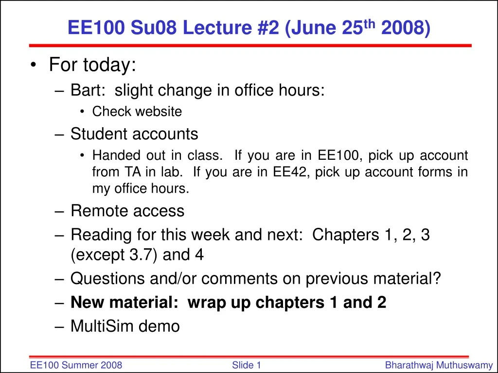
This notice provides information about a slight change in office hours, where to pick up student accounts, and the reading assignments for the next class. It also includes a demonstration of the Sign Convention for Power.

E N D
EE100 Su08 Lecture #2 (June 25th 2008) • For today: • Bart: slight change in office hours: • Check website • Student accounts • Handed out in class. If you are in EE100, pick up account from TA in lab. If you are in EE42, pick up account forms in my office hours. • Remote access • Reading for this week and next: Chapters 1, 2, 3 (except 3.7) and 4 • Questions and/or comments on previous material? • New material: wrap up chapters 1 and 2 • MultiSim demo
Sign Convention for Power • If p > 0, power is being delivered to the box. • If p < 0, power is being extracted from the box. Passive sign convention p = vi p = -vi i i i i _ v + _ v + + v _ + v _
Power • If an element is absorbing power (i.e. if p > 0), positive charge is flowing from higher potential to lower potential. • p = vi if the “passive sign convention” is used: i i _ v + + v _ or How can a circuit element absorb power? By converting electrical energy into heat (resistors in toasters), light (light bulbs), or acoustic energy (speakers); by storing energy (charging a battery).
Power Calculation Example Find the power absorbed by each element: Conservation of energy total power delivered equals total power absorbed Aside: For electronics these are unrealistically large currents – milliamperes or smaller is more typical p (W) vi (W) 918 - 810 - 12 - 400 - 224 1116
Circuit Elements • 5 ideal basic circuit elements: • voltage source • current source • resistor • inductor • capacitor • Many practical systems can be modeled with just sources and resistors • The basic analytical techniques for solving circuits with inductors and capacitors are similar to those for resistive circuits active elements, capable of generating electric energy passive elements, incapable of generating electric energy
Electrical Sources • An electrical source is a device that is capable of converting non-electric energy to electric energy and vice versa. Examples: • battery: chemical electric • dynamo (generator/motor): mechanical electric (Ex. gasoline-powered generator, Bonneville dam) • Electrical sources can either deliver or absorb power
Ideal Voltage Source • Circuit element that maintains a prescribed voltage across its terminals, regardless of the current flowing in those terminals. • Voltage is known, but current is determined by the circuit to which the source is connected. • The voltage can be either independent or dependent on a voltage or current elsewhere in the circuit, and can be constant or time-varying. Device symbols: vs + vs=m vx + vs=r ix + _ _ _ independent current-controlled voltage-controlled
Ideal Current Source • Circuit element that maintains a prescribed current through its terminals, regardless of the voltage across those terminals. • Current is known, but voltage is determined by the circuit to which the source is connected. • The current can be either independent or dependent on a voltage or current elsewhere in the circuit, and can be constant or time-varying. Device symbols: is is=a vx is=b ix independent current-controlled voltage-controlled
R Electrical Resistance • Resistance: the ratio of voltage drop and current. The circuit element used to model this behavior is the resistor. Circuit symbol: Units: Volts per Ampere ≡ ohms (W) • The current flowing in the resistor is proportional to the voltage across the resistor: v = i R where v = voltage (V), i = current (A), and R = resistance (W) Georg Simon Ohm 1789-1854 (Ohm’s Law)
Electrical Conductance • Conductance is the reciprocal of resistance. Symbol: G Units: siemens (S) or mhos ( ) Example: Consider an 8 W resistor. What is its conductance? W Werner von Siemens 1816-1892
Short Circuit and Open Circuit • Short circuit • R = 0 no voltage difference exists • all points on the wire are at the same potential. • Current can flow, as determined by the circuit • Open circuit • R = no current flows • Voltage difference can exist, as determined by the circuit
Example: Power Absorbed by a Resistor p = vi = ( iR )i = i2R p = vi = v ( v/R ) = v2/R Note that p > 0 always, for a resistor a resistor dissipates electric energy Example: • Calculate the voltage vg and current ia. • Determine the power dissipated in the 80W resistor.
Summary • Current = rate of charge flow i = dq/dt • Voltage = energy per unit charge created by charge separation • Power = energy per unit time • Ideal Basic Circuit Elements • two-terminal component that cannot be sub-divided • described mathematically in terms of its terminal voltage and current • An ideal voltage source maintains a prescribed voltage regardless of the current in the device. • An ideal current source maintains a prescribed current regardless of the voltage across the device. • A resistor constrains its voltage and current to be proportional to each other: v = iR (Ohm’s law)
Summary (cont’d) • Passive sign convention • For a passive device, the reference direction for current through the element is in the direction of the reference voltage drop across the element
Current vs. Voltage (I-V)Characteristic • Voltage sources, current sources, and resistors can be described by plotting the current (i) as a function of the voltage (v) i + v _ Passive? Active?
Vs>0 I-V Characteristic of Ideal Voltage Source i • Plot the I-V characteristic for vs > 0. For what values of i does the source absorb power? For what values of i does the source release power? • Repeat (1) for vs < 0. • What is the I-V characteristic for an ideal wire? i a + Vab _ + vs _ i=0 v b Vs>0 i<0 release power; i>0 absorb power
Vs<0 I-V Characteristic of Ideal Voltage Source i 2. Plot the I-V characteristic for vs < 0. For what values of i does the source absorb power? For what values of i does the source release power? i a + Vab _ + vs _ v b Vs<0 i>0 release power; i<0 absorb power
I-V Characteristic of Ideal Voltage Source 3. What is the I-V characteristic for an ideal wire? i a + Vab _ + vs _ b
I-V Characteristic of Ideal Current Source i • Plot the I-V characteristic for is > 0. For what values of v does the source absorb power? For what values of v does the source release power? i + v _ is v V>0 absorb power; V<0 release power
Short Circuit and Open Circuit Wire (“short circuit”): • R = 0 no voltage difference exists (all points on the wire are at the same potential) • Current can flow, as determined by the circuit Air (“open circuit”): • R = no current flows • Voltage difference can exist, as determined by the circuit
I-V Characteristic of Ideal Resistor i • Plot the I-V characteristic for R = 1 kW. What is the slope? i a + v _ R v b a a + Vab _ Vab R R b b
Construction of a Circuit Model • The electrical behavior of each physical component is of primary interest. • We need to account for undesired as well as desired electrical effects. • Simplifying assumptions should be made wherever reasonable.
Node: A point where two or more circuit elements are connected Branch: A path that connects two nodes Terminology: Nodes and Branches
Circuit Nodes and Loops • A node is a point where two or more circuit elements are connected. • A loop is formed by tracing a closed path in a circuit through selected basic circuit elements without passing through any intermediate node more than once
Kirchhoff’s Laws • Kirchhoff’s Current Law (KCL): • The algebraic sum of all the currents entering any node in a circuit equals zero. • Kirchhoff’s Voltage Law (KVL): • The algebraic sum of all the voltages around any loop in a circuit equals zero. Gustav Robert Kirchhoff 1824-1887
Use one node as the reference (the “common” or “ground” node) – label it with a symbol The voltage drop from node x to the reference node is called the node voltagevx. The voltage across a circuit element is defined as the difference between the node voltages at its terminals Example: Notation: Node and Branch Voltages –v1 + a R1 b + va _ + vb _ + vs R2 _ c REFERENCE NODE
Using Kirchhoff’s Current Law (KCL) • Use reference directions to determine whether currents are “entering” or “leaving” the node – with no concern about actual current directions Consider a node connecting several branches: i2 i3 i1 i4
Formulations of Kirchhoff’s Current Law (Charge stored innode is zero.) Formulation 1: Sum of currents entering node = sum of currents leaving node Formulation 2: Algebraic sum of currents entering node = 0 • Currents leaving are included with a minus sign. Formulation 3: Algebraic sum of currents leaving node = 0 • Currents entering are included with a minus sign.
A Major Implication of KCL • KCL tells us that all of the elements in a single branch carry the same current. • We say these elements are connected in series. Current entering node = Current leaving node i1 = i2
KCL Example 3 formulations of KCL: 1. 2. 3. Currents entering the node: Currents leaving the node: -10 mA i 5 mA 15 mA