Download
1 / 43
430 likes | 436 Views
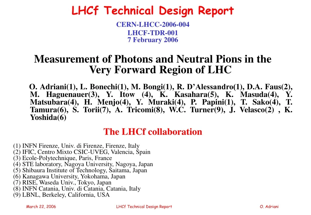
LHCf Technical Design Report CERN-LHCC-2006-004 LHCF-TDR-001 7 February 2006 Measurement of Photons and Neutral Pions in the Very Forward Region of LHC

E N D
LHCf Technical Design Report CERN-LHCC-2006-004 LHCF-TDR-001 7 February 2006 Measurement of Photons and Neutral Pions in the Very Forward Region of LHC O. Adriani(1), L. Bonechi(1), M. Bongi(1), R. D’Alessandro(1), D.A. Faus(2), M. Haguenauer(3), Y. Itow (4), K. Kasahara(5), K. Masuda(4), Y. Matsubara(4), H. Menjo(4), Y. Muraki(4), P. Papini(1), T. Sako(4), T. Tamura(6), S. Torii(7), A. Tricomi(8), W.C. Turner(9), J. Velasco(2) , K. Yoshida(6) The LHCf collaboration (1) INFN Firenze, Univ. di Firenze, Firenze, Italy (2) IFIC, Centro Mixto CSIC-UVEG, Valencia, Spain (3) Ecole-Polytechnique, Paris, France (4) STE laboratory, Nagoya University, Nagoya, Japan (5) Shibaura Institute of Technology, Saitama, Japan (6) Kanagawa University, Yokohama, Japan (7) RISE, Waseda Univ., Tokyo, Japan (8) INFN Catania, Univ. di Catania, Catania, Italy (9) LBNL, Berkeley, California, USA LHCf Technical Design Report O. Adriani
Highlight of the talk • Short ‘history’ • Review of physics • Detector overview and background study (after November 16th LHCC) • Progress report on cabling, safety, installation, trigger, luminosity measurement, etc • Possible running scenario • Summary Many important technical aspects can not be covered in this presentation TDR for details LHCf Technical Design Report O. Adriani
Letter Of Intent: May 2004 Technical report: September 2005 Technical Design Report: February 2006 LHCC October 2005 comments: • The physics goals are worthwhile and the proposed experiment appears suited to achieve them • A few key issues require immediate consideration, and documentation in the update of the TP: • establish official contact with the relevant structures in the AT/AB departments, • as well as in ATLAS etc… • appoint a technical coordinator (possibly located at CERN?) • consider and document safety issues • On the other hand: the TP is not sufficiently detailed and fails to provide a solid and • compelling evidence that the above expectations are justified TDR was released to answer to these questions LHCf Technical Design Report O. Adriani
Xmax(g/cm2) Energy (eV) Main problems in High Energy Cosmic Rays (E>1015eV) • Composition • Spectrum / GZK Cutoff LHCf Technical Design Report O. Adriani
Development of atmospheric showers Simulation of an atmospheric shower due to a 1019 eV proton. • The dominant contribution to the energy flux is in the very forward region ( 0) • In this forward region the highest energy available measurements of p0 cross section were done by UA7 (E=1014 eV, y = 5÷7) The direct measurement of the p production cross section as function of pT is essential to correctly estimate the energy of the primary cosmic rays (LHC: 1017 eV) LHCf Technical Design Report O. Adriani
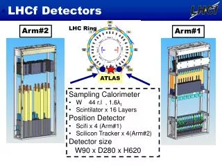
Experimental Method:2 independent detectors on both sides of IP Detector I Tungsten Scintillator Scintillating fibers Detector II Tungsten Scintillator Silicon mstrips INTERACTION POINT 140 m 140 m Beam line • Redundancy • Background rejection (especially beam-gas) IP1 was definitely chosen in October 2005 LHCf Technical Design Report O. Adriani
Here the beam pipe splits in 2 separate tubes. • Charged particle are swept away by magnets!!! • We will cover up to y Detectors will be installed in the TAN region, 140 m away from the Interaction Point, in front of luminosity monitors LHCf Technical Design Report O. Adriani
box ~ (15×15×40) cm3 The TAN and LHCf manipulator marble shielding boxes for DAQ electronic LHCf Technical Design Report O. Adriani
ARM #1 detector scintillating fibers tungsten layers • 2 towers (2.02.0cm2 and 4.04.0 cm2) • ~47 r.l. (22 2.1 r.l. tungsten layers) • 16 scintillator layers (3 mm thick) • 4 pairs of scintillating fiber layers for tracking purpose (two orthogonal directions) scintillators Energy Impact point (h) LHCf Technical Design Report O. Adriani
We used LHC style electronics and readout ARM #2 detector • 2 towers (2.52.5cm2 and 3.53.5 cm2) • 44 r.l. (22 2 r.l. tungsten layers) • 16 scintillator layers (3 mm thick) • 4 pairs of silicon microstrip layers for tracking purpose (X and Y directions) Energy silicon layers Impact point (h) See TDR for details… scintillators tungsten layers LHCf Technical Design Report O. Adriani
Transverse projection of detector #1 in the TAN slot LHCf Technical Design Report O. Adriani
Transverse projection of detector #2 in the TAN slot LHCf Technical Design Report O. Adriani
LHCf physics measurements • Single photon spectrum • p0 fully reconstructed (1 g in each tower) p0 reconstruction is an important tool for energy calibration (p0 mass constraint) Basic concept: • minimum 2 towers (p0 reconstruction) • Smallest tower on the beam (multiple hits) • Dimension of the tower Moliere radius • Maximum acceptance (given the LHC constraints) Simulation is used to understand the physics performances Beam test in Summer 2004 (Energy resolution) LHCf Technical Design Report O. Adriani
Development of showers in Arm #2Eγ= 500 GeV Fluka based simulation LHCf Technical Design Report O. Adriani
Position resolution of Arm #2 calorimeter 7 mm for 1.8 TeV photons LHCf Technical Design Report O. Adriani
Some runs with LHCf vertically shifted few cm will allow to cover the whole kinematical range Single g geometrical acceptance LHCf Technical Design Report O. Adriani
A vertical beam crossing angle > 0 will increase the acceptance of LHCf Acceptance map on PTg-Eγ plane 140 Beam crossing angle Detectable events LHCf Technical Design Report O. Adriani
Monte Carlo g ray energy spectrum (5% Energy resolution is taken into account) 106 generated LHC interactions 1 minute exposure Discrimination between various models is feasible Quantitative discrimination with the help of a properly defined c2 discriminating variable based on the spectrum shape (see TDR for details) LHCf Technical Design Report O. Adriani
p0 geometrical acceptance Arm #2 Arm #1 LHCf Technical Design Report O. Adriani
Energy spectrum of π0 expected from different models(Typical energy resolution of gis 3 % at 1TeV) LHCf Technical Design Report O. Adriani
p0 mass resolution Arm #1 DE/E=5% 200 mm spatial resolution Dm/m = 5% LHCf Technical Design Report O. Adriani
Model dependence of neutron energy distribution Original n energy 30% energy resolution LHCf Technical Design Report O. Adriani
Results of the beam test at H4 line LHCf Technical Design Report O. Adriani
Summary 1 • We will be able to measure π0 mass with ±5% resolution. • We will be able to distinguish the models by measurements of π0 and γ • We will be able to distinguish the models by measurements of n • Beam crossing angle ≠0 and/or vertical shifts of LHCf by few cm will allow more complete physics measurements LHCf Technical Design Report O. Adriani
Estimation of the background • beam-beam pipe answered (on Nov.16), E γ(signal) > 200 GeV, OK background < 1% (see details in TDR) • beam-gas answered (on Nov.16) It depends on the beam condition background < 1% (under 10-10 Torr)(see details in TDR) • beam halo-beam pipe It has been newly estimated from the beam loss rate Background < 10% (conservative value) (see details in TDR) LHCf Technical Design Report O. Adriani
Background from the beam pipe LHCf Technical Design Report O. Adriani
Support from CERN for Integration • We had (and we will have!) continuous meetings with CERN teams • General : TS/LEA • Integration: TS/IC • Cabling: TS/EL • Cooling: TS/CV • Survey (cabling): TS/SU • Safety: SG • Radiation protection: SC/RP • ATLAS, BRAN, ZDC teams • Engineering Change Request (ECR) has been submitted and approved last week: • Machine people are well informed about LHCf • No problems foreseen for the LHCf installation at the LHC startup • Main item to be discussed is the BRAN (LUMI) interference (see later) A very useful TAN integration workshop has been organized on March 10 at CERN (TS/LEA). All the involved groups were present!!!! Takashi Sako: Technical coordinator LHCf Technical Design Report O. Adriani
Rack, data taking and trigger*Two racks will be located at Y26-05.A1 and Y27-05.A1 at USA15 hall of ATLAS counting room*The trigger signal will be created after 1.4 msec of the beam crossing 1st level trigger 2nd level trigger LHCf Technical Design Report O. Adriani
Cables • TS/LEA is fully aware of the cables stuff • Demande Installation Cable (DIC) has been submitted • The order is under way • Cables will be pulled in the July-September period See TDR for details LHCf Technical Design Report O. Adriani
Radiation Safety • We have estimated the total radiation dose and activation of LHCf installed in the TAN • The activation after 30 days of operation and 1 day cool-down at ℒ ≈ 1030 /cm-2sec-1 is • 10-3 – 10-2 mSV/hr • Remote handling procedures may not be needed • We are in contact with SC/RP peoples LHCf Technical Design Report O. Adriani
Installation plan • A detailed installation plan has been agreed with TS/LEA • Arm #1: 128 days from May 2006 to November 2006 • Cables tray • Cables • Detector • Manipulator • Electronics • Tests • Arm #2: 210 days from May 2006 to February 2007, similar to #1 • LHCf Arm #1 and #2 will be ready to • take the first LHC data….. • (Beam test of the complete Arm #1 and part of the • Arm #2 is foreseen August 24th, September 3rd at SPS) LHCf Technical Design Report O. Adriani
LHCf and LUMI monitor (BRAN) LUMI monitor (BRAN) inside TAN is beyond LHCf (replacing 4th copper bar) IP1 Cu Bar / ZDC LHCf Cu Bar / ZDC LHCf Lumi Lumi • LHCf 44 X0 thickness • But the thickness is not uniform (diamond shaped towers, no material outside towers) • LUMI Monitor see different thickness of material in different geometrical regions • different response as function of the impact point position (calibration is required) • reduction of the number of neutral particles hitting BRAN • possible dependence of the detector response as function of the beam position? • We are studying the problem of the LHCf effect on LUMI together with W.C. Turner and his group from LBNL. CERN LHC and ATLAS people are informed about these studies (see TAN integration workshop as last example) LHCf Technical Design Report O. Adriani
Effect of LHCf on BRAN measurement The effect of LHCf on BRAN measurements has been studied in the last months by simulation • Reduction of shower particles at BRAN • Position dependence on beam displacement (question from machine peoples: if we shift by 1 mm the real beam, does the center of the measured neutral energy shifts by 1 mm?) Answer: • If beam displacement is < a few mm, difference is < 10% • LHCf itself can provide the center of neutral flux • LHCf can give some info on Luminosity measurement LHCf Technical Design Report O. Adriani
Arm #1 Arm #2 H.Menjo Typical reduction factor: 0.3 BRAN response vs beam position reduction factor for BRAN: # of neutral hadrons in the LHCf aperture / # of neutral hadrons in the whole aperture (inelastic interactions generated with DPMJET3 model) LHCf Technical Design Report O. Adriani
If the position of beam center stays within a few mm from the beam-pipe center, the reduction factors do not change more than 10% 1 x 1 cm2 1 x 1 cm2 BRAN response vs beam position (2) Relative change of the reduction factors for BRAN with respect to the nominal value (center of the beam: nominal one) Arm #1 Arm #2 LHCf Technical Design Report O. Adriani H.Menjo
Beam test result s ~ 200mm Determination of neutral flux center by LHCf particles LHCf can measure (and provide to LHC) the center of neutral flux from the collisions Position sensitive layers If the center of the neutral flux hits LHCf << 1 mm resolution LHCf Technical Design Report O. Adriani
Summary 2 • LHCf can do the proposed physics measurements (background is under control) • Integration with CERN infrastructures and other groups involved is well established • The interference with BRAN/LUMI measurement is under study; a ‘smooth’ solution seems to be feasible • LHCf can provide on-line useful information to machine people (Relative luminosity, beam position, beam-gas rate etc.) Important issue to be considered in detail from now on LHCf Technical Design Report O. Adriani
Optimal LHCf run conditions • Beam parameters used for commissioning are good for LHCf!!! ( No radiation problem for 10kGy by a “year” operation with this luminosity ) LHCf Technical Design Report O. Adriani
From H. Burkhardt TAN workshop presentation LHCf Technical Design Report O. Adriani
LHCf possible running scenario • Phase-I • Parasite running during the early stage of LHC commissioning in 2007 • Remove the detector when luminosity reaches 1030cm-2s-1 level for radiation reason and reinstall the 3 Cu bars (no activation problems) • Phase-II • Re-install the detector at the next opportunity of low luminosity run after removal of Cu bars (activated to 10-1 mSv/hr, manipulator?) • Phase-III • Future extension for p-A, A-A run with upgraded detectors. Detailed running scenario should be discussed and agreed with LHCC, Machine people, Atlas people…. LHCf Technical Design Report O. Adriani
Budgetshare table Contributions from different countries Japan: 600KCHF Italy: 300KCHF France: under negotiation • Detector # 1Detector#2 • Tungsten JapanJapan • MechanicsJapanJapan • Plastic ScintillatorsJapanJapan • Scintillating fibersJapan----------- • Silicon sensors-----------INFN • Photomultipliers for scintillatorJapanJapan • Multianode photomultipliers for fibers • Japan----------- • Preamplifiers for silicon-----------INFN • Hybrid and Kapton for silicon-----------INFN • Readout electronics for fibers (VA based) • Japan----------- • Readout electronics for silicon----------- INFN • VME Interface board for fibersJapan----------- • VME Interface board for silicon-----------INFN • VME ADC boards for scintillators • Japan/INFNJapan/INFN • VME crateJapanINFN • Low voltage Power SupplyJapanINFN • High voltage Power Supply for scintillators • JapanJapan/INFN • High voltage Power Supply for fibers • Japan----------- LHCf Technical Design Report O. Adriani
Concluding Remarks • LHCf physics measurements are extremely useful for cosmic ray physics (see LOI 2004) • A huge work has been done to complete the TDR, answering to the LHCC and referees comments • The detectors have been carefully optimized • The integration with other activities possibly interfering with LHCf is well established (ATLAS, BRAN/LUMI, TAN related experiment, safety, cabling etc.) • ECR has been approved last week • LHCf will be ready to take the first LHC data… LHCf Technical Design Report O. Adriani