Download
1 / 36
360 likes | 380 Views
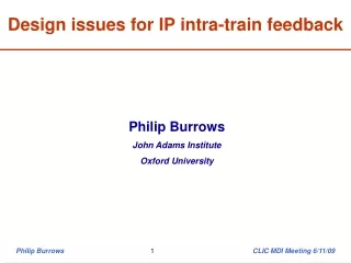
Design issues for IP intra-train feedback. Philip Burrows John Adams Institute Oxford University. Outline. General considerations for intra-train feedback system ILC RDR layout Engineering integration issues Prototype hardware (FONT systems) Summary.

E N D
Design issues for IP intra-train feedback Philip Burrows John Adams Institute Oxford University Philip Burrows CLIC MDI Meeting 6/11/09
Outline • General considerations for intra-train feedback system • ILC RDR layout • Engineering integration issues • Prototype hardware (FONT systems) • Summary Philip Burrows CLIC MDI Meeting 6/11/09
IP intra-train feedback system - concept • Last line of defence against relative beam misalignment • Measure vertical position of outgoing beam and hence beam-beam kick angle • Use fast amplifier and kicker to correct vertical position of beam incoming to IR FONT – Feedback On Nanosecond Timescales (JAI/Oxford, Valencia, CERN, DESY, KEK,SLAC) Philip Burrows CLIC MDI Meeting 6/11/09
FONT Team • JAI/Oxford: • Philip Burrows • Glenn Christian • Hamid Dabiri Khah • Javier Resta Lopez • Colin Perry • Graduate students: • Christina Swinson • Ben Constance • Robert Apsimon • Douglas Bett • Alexander Gerbershagen Philip Burrows CLIC MDI Meeting 6/11/09
General considerations (1) 1. IP position feedback: hardware located near IP kicker at 90 degrees w.r.t. IP 2. IP angle feedback: hardware ideally located near IP kicker in phase w.r.t. IP 3. Additional possibilities: (bunch-by-bunch) luminosity scan system (from BEAMCAL) information from alignment systems (eg. QD0 etc.) ‘feed-forward’ information from upstream in machine (eg. DR) … Philip Burrows CLIC MDI Meeting 6/11/09
General considerations (2) Time structure of bunch train: ILC (500 GeV): c. 3000 bunches w. c. 300 ns separation CLIC (3 TeV): c. 300 bunches w. c. 0.5 ns separation Feedback latency: ILC: O(100ns) latency budget allows digital approach CLIC: O(10ns) latency requires analogue approach Recall speed of light: c = 30 cm / ns: FB hardware should be close to IP (especially for CLIC!) Philip Burrows CLIC MDI Meeting 6/11/09
IP position feedback latency Designed for (bunch-by-bunch) position correction of beams at IP Latency: 1. Beam flight time IP BPM 2. Signal processing, FB calculation 3. Amplifier + kicker response time 4. Cable delays 5. Beam flight time kicker IP 3 5 4 1 2 Philip Burrows CLIC MDI Meeting 6/11/09
Latency issues • BPM or kicker further from IP • longer beam flight distance • increase latency (3ns per metre) • Electronics further from beamline • longer cable runs • increase latency (4-5ns per metre) • FB system electronics latency Philip Burrows CLIC MDI Meeting 6/11/09
ILC RDR Design (schematic) 1. IP position feedback: provide IP beam position correction at +- 50 sigma_y level i.e. +- 300 nm of vertical beam motion at IP 2. IP angle feedback: hardware located few 100 metres upstream conceptually very similar to position FB, (arguably) less critical 3. Bunch-by-bunch luminosity signal (from BEAMCAL) ‘special’ systems requiring dedicated hardware + data links Philip Burrows CLIC MDI Meeting 6/11/09
IP feedback engineering considerations System component locations + specs listed in ILC RDR Philip Burrows CLIC MDI Meeting 6/11/09
Final Doublet Region (SiD for illustration) - Oriunno Reacting bars QD0 Cam/support QF Spool tubes Opening 2 m on the beam Philip Burrows CLIC MDI Meeting 6/11/09
Final Doublet Region (SiD for illustration) - Oriunno Reacting bars QD0 Cam/support QF Spool tubes Opening 2 m on the beam Philip Burrows CLIC MDI Meeting 6/11/09
IP feedback engineering considerations System component locations + specs listed in ILC RDR No detailed engineering work done in terms of: actual designs of BPM and kicker integration into beamline design However, components are envisaged to be ‘standard’: Stripline BPM c. 10-20cm long (ATF: 12.5cm) Stripline kicker c. 30-60cm long (ATF ~ 30cm) Stripline radius c. 1-2cm(ATF ~ 1cm) Probably want to customise designs to fit into tight beamline environment Philip Burrows CLIC MDI Meeting 6/11/09
BPM engineering issues • Connections to BEAMCAL, QD0 cryostat? • Bellows? • Alignment/mover system? • Shorten pickoffs? • Electronics off to side and shielded? • Define cable runs: door opening, push-pull? Philip Burrows CLIC MDI Meeting 6/11/09
Final Doublet Region (SiD for illustration) - Oriunno Reacting bars QD0 Cam/support QF Spool tubes Opening 2 m on the beam Philip Burrows CLIC MDI Meeting 6/11/09
Kicker engineering issues • Real-estate more generous • Does warm section move with detector in push-pull? • Amplifier detector-side or machine-side of break? • Flanges, bellows, at both ends? • Shorten pickoffs? Philip Burrows CLIC MDI Meeting 6/11/09
Amplifier engineering issues FONT4 amplifier performance: Kicker 30cm long, 2cm aperture, 1kW drive 100 nrad deflection (250 GeV beam) lever arm 4m +- 400 nm at IP ( > 50 sigma_y) Kick ~ l, 1/r, sqrt(P), 1/p … Philip Burrows CLIC MDI Meeting 6/11/09
Feedback Instrumentation & Vacuum Design (Malyshev, Oriunno) L<1 m Moves with Detector QD0 IP Stationary BPM Kicker • Present vacuum requirements : • P < 1nT in the BDS • P < 100nT in the experimental region • We may rely on the cryopumping from QD0 • We do not need extra pumps • We do not need periodic bake out in situ. • Open point : • The beam instrumentation required • Shut-off valves Integration study Philip Burrows CLIC MDI Meeting 6/11/09
CLIC_ILD Detector Concept: Forward Region Version 3 Nov. 2009 (by André Sailer) ECal end-cap HCal end-cap Yoke end-cap (partial) LumiCal BeamCal QD0 (partial) Philip Burrows CLIC MDI Meeting 6/11/09
CLIC_ILD Detector Concept: Forward Region Version 3 Nov. 2009 (by André Sailer) ECal end-cap HCal end-cap Yoke end-cap (partial) LumiCal BeamCal QD0 (partial) Philip Burrows CLIC MDI Meeting 6/11/09
Summary of engineering issues Several prototype intra-train feedbacks developed by FONT – see next Detailed mechanical/integration engineering needs to be done for ILC and more work on conceptual design for CLIC Radiation environment for BPM electronics, feedback electronics, kicker amplifier: radiation tolerance, locations, shielding … EM interference: Pickup on BPM or kicker Broadcast RF (eg. to detector!) Ground loops Interface to BEAMCAL for luminosity scan system Philip Burrows CLIC MDI Meeting 6/11/09
ILC feedback prototype status Philip Burrows CLIC MDI Meeting 6/11/09
FONT4 ILC prototype at KEK/ATF Kicker BPM 1 BPM 2 BPM 3 e- 1.3 GeV Drive amplifier Analogue BPM processor 3 bunches, 140-154ns spacing Digital feedback Philip Burrows CLIC MDI Meeting 6/11/09
FONT4 ILC prototype at KEK/ATF Kicker BPM 1 BPM 2 BPM 3 e- Drive amplifier Analogue BPM processor Digital feedback Philip Burrows CLIC MDI Meeting 6/11/09
FONT status • FONT4 basic operation demonstrated in 2008 running: • beam feedback along single axis (y) with few micron resolution Philip Burrows CLIC MDI Meeting 6/11/09
CLIC feedback prototype status Philip Burrows CLIC MDI Meeting 6/11/09
FONT Prototype Analogue Feedback Systems • NLCTA: 65 MeV beam, 170ns train, 87ps bunch spacing • FONT1 (2001-2): • First demonstration of closed-loop FB: latency 67ns • 10/1 beam position correction • FONT2 (2003-4): • Improved demonstration of FB: latency 54ns • real time charge normalisation with logarithmic amplifiers • beam flattener to straighten train profile • solid-state amplifier • ATF: 1.3 GeV beam, 56ns train, 2.8ns bunch spacing • FONT3 (2004-5): • Ultra-fast demonstration of FB: latency 23 ns • 3 stripline BPMs • high-power solid-state amplifier Philip Burrows CLIC MDI Meeting 6/11/09
FONT2 beamline installation at SLAC NLCTA(65 MeV 170ns-long train @ 87ns spacing) Dipole and kickers BPMs Philip Burrows CLIC MDI Meeting 6/11/09
FONT2 results: feedback BPM Beam starting positions beam start beam end Beam flattener on Feedback on 4 1 2 3 Delay loop on Philip Burrows CLIC MDI Meeting 6/11/09
FONT3ATF: 1.3 GeV beam, 56ns-long train @ 2.8ns spacing Adjustable-gap kicker BPM ML11X BPM ML12X BPM ML13X Superfast amplifier Superfast BPM processor Aim: TOTAL latency < 20 ns Feedback Philip Burrows CLIC MDI Meeting 6/11/09
FONT3: latency budget • Time of flight kicker – BPM: 4ns • Signal return time BPM – kicker: 6ns • Irreducible latency: 10ns • BPM processor: 5ns • Amplifier + FB: 5ns • Electronics latency: 10ns • Total latency budget: 20ns • Allows 56/20 = 2.8 periods during bunchtrain Philip Burrows CLIC MDI Meeting 6/11/09
FONT3: Beamline Installation Philip Burrows CLIC MDI Meeting 6/11/09
FONT3: Results (June 3 2005)40 pulses per position setting Philip Burrows CLIC MDI Meeting 6/11/09
FONT3: Results (June 3 2005):Delay-loop feedback w. latency 23 ns 56ns bunchtrain 200um FB on 23ns FB + delay loop on Philip Burrows CLIC MDI Meeting 6/11/09
FONT1,2,3: Summary 67 ns 54 ns 23 ns Fast enough for CLIC intra-train FB! Philip Burrows CLIC MDI Meeting 6/11/09
Other updates • Since CLIC Workshop Javier Resta Lopez has updated the luminosity performance simulations: • Improved ground-motion study • IP intra-train FB + BDS (slow) orbit SVD FB • Integrated luminosity recovery over bunchtrain duration • Slides appended to today’s meeting page – suggest future presentation • Beam-related backgrounds (e+e-, photons) produced near IP are a major source of concern for CLIC FB hardware • T-480 experiment using SLAC 30 GeV beam to create huge flux of EM backgrounds in a material model of IR – worth future presentation Philip Burrows CLIC MDI Meeting 6/11/09