Download
1 / 26
420 likes | 806 Views
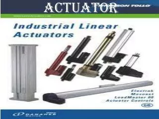
Development of single actuator circuits. Control of a single-acting cylinder. Control of a double-acting cylinder. Allocation of devices to signal flow. Control chain example. Direct control of a single-acting cylinder. Direct control of a double-acting cylinder. Using 4/2 DCV.

E N D
Direct control of a double-acting cylinder Using 4/2 DCV Using 5/2 DCV
Indirect control of a double-acting cylinder Using 5/2 DCV Using 4/2 DCV
Circuit layout The piston rod of a double-acting pneumatic cylinder advances if either a manual push button or a foot pedal is operated. The cylinder returns to its starting position slowed down after fully extended. The piston rod will return provided the manual actuators have been released.
The logic AND function Supply pressure from 1S1 AND 1S2 simultaneously
The logic AND function Example: The piston rod of cylinder 1A is to advance only if a • workpiece is inserted in the workpiece retainer, • a guard has been lowered • and the operator presses the push button valve. Upon the release of the push button or if the guard is no longer in the lower position, the cylinder 1A is to retract to the initial position.
The logic AND function The logic AND operation of the output signals of valves 1S1,AND 1S2 AND 1S3 is checked by the dual-pressure valves 1V1 and 1V2.
The logic OR function Supply pressure from 1S1 OR 1S2
The logic OR function The logic OR operation of the output signals of valves 1S1 and 1S2 is checked by the shuttle valve 1V1.
Memory circuit and speed control of a cylinder Example: A double-acting cylinder is to be used to transfer parts. The cylinder is to fully advance when a push button is operated and then retract automatically. Full extension is confirmed by a roller lever valve. The cylinder is to continue forward even if the push button is released before full extension is reached. The speed of the cylinder is to be adjustable in both directions of motion
The quick exhaust valve Example: The combined actuation of a manually actuated valve and a roller lever valve advances a forming tool on an edge-folding device. The forming tool is driven by a double-acting cylinder. For rapid forward travel, the circuit utilizes a quick exhaust valve. The retracting speed is to be adjustable. If either of the two valves are released, the tool returns to its initial position.
The quick exhaust valve In the initial position, the inserted workpiece actuates the roller lever valve 1S2. The quick exhaust valve 1V4 is closed to atmosphere, pressure is applied at the piston rod side of the cylinder 1A, and the piston rod remains in the retracted status. If one of the two valves 1S1 or 1S2 is released, the AND condition at the dual-pressure valve 1V1 is no longer met. The final control element 1V2 switches, the quick exhaust valve 1V4 closes and the piston rod retracts.
Circuit diagram withpressure sequence valve Pressure sequence valves are installed in pneumatic controls where a specific pressure is required for a switching operation (pressure dependent controls).
Pressure dependent control; embossing of plastic components A plastic component is embossed using a die powered by a double acting cylinder. The return of the die is to be effected when the cylinder rod has fully extended to the embossing position and the preset pressure is reached. A roller lever valve is to be used to confirm full extension. The signal for retracting must only be generated when the piston rod has reached the embossing position. The pressure in the piston chamber is indicated by a pressure gauge.
Pressure dependent control In the initial position, valves 1S1 and 1S2 are unactuated, pressure is applied at the piston rod side of the cylinder 1A and the piston rod remains in the retracted state. If necessary, the circuit needs to be put into its initial position with the help of the manual override on the control element 1V2. A signal is applied at the control port 14 of the control element 1V2, if the push button 1S1 is actuated. The valve 1V2 switches, pressure is applied at the piston side of the cylinder 1A, and the piston rod advances. If the push button 1S1 is released, the switching position of the double pilot valve 1V2 does not change due to its memory function.
The time delay valve A double-acting cylinder is used to press together two components. Upon operation of a push button, the clamping cylinder slowly advances. Once the fully extended position is reached, the cylinder is to remain for a time of 6 seconds and then immediately retract to the initial position. A new start cycle is only possible after the cylinder has fully retracted and after a delay 5 seconds. During this delay the finished part is manually removed and replaced with new parts. The retracting speed is to be rapid, but adjustable.
The time delay valve A double-acting cylinder is used to press together two components. Upon operation of a push button, the clamping cylinder slowly advances. Once the fully extended position is reached, the cylinder is to remain for a time of 6 seconds and then immediately retract to the initial position. A new start cycle is only possible after the cylinder has fully retracted and after a delay 5seconds. During this delay the finished part is manually removed and replaced with new parts. The retracting speed is to be adjustable.