Download
1 / 50
500 likes | 695 Views
Database Systems I Week 2: The Entity-Relationship Model. Overview of Database Development. Requirements Analysis / Ideas. High-Level Database Design. Conceptual Database Design / Relational Database Schema. Physical Database Design / Relational DBMS. Similar to software development.

E N D
Overview of Database Development Requirements Analysis / Ideas High-Level Database Design Conceptual Database Design / Relational Database Schema Physical Database Design / Relational DBMS Similar to software development
Overview of Database Development • Requirements Analysis • What data are to be stored in the enterprise? • What are the required applications? • What are the most important operations? • High-level database design • What are the entities and relationships in the enterprise? • What information about these entities and relationships should we store in the database? • What are the integrity constraints or business rules that hold? • ER model or UML to represent high-level design
Overview of Database Development • Conceptual database design • What data model to implement for the DBS?E.g., relational data model • Map the high-level design (e.g., ER diagram) to a (conceptual) database schema of the chosen data model. • Physical database design • What DBMS to use? • What are the typical workloads of the DBS? • Build indexes to support efficient query processing. • What redesign of the conceptual database schema is necessary from the point of view of efficient implementation?
Entity-Relationship Model • Short: ER model. • A lot of similarities with other modeling languages such as UML. • Concepts • Entities / Entity sets, • Attributes, • Relationships/ Relationship sets, and • Constraints. • Offers more modeling concepts than the relational data model (which only offers relations). • Closer to the way in which people think.
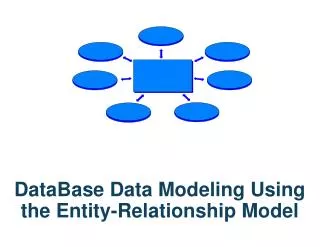
Entity-Relationship Diagrams • An Entity-Relationship diagram (ER diagram) is a graph with nodes representing entity sets, attributes and relationship sets. • Entity sets denoted by rectangles. • Attributes denoted by ovals. • Relationship sets denoted by diamonds. • Edges (lines) connect entity sets to their attributes and relationship sets to their entity sets. since name dname ssn budget lot did Works_In Employees Departments
Entities and Entity Sets • Entity: Real-world object distinguishable from other objects • e.g. employee Miller. • Entity can be physical or abstract object. • An entity is associated with the attributes describing its properties. • Attribute values are atomic • e.g. strings, integer or real numbers. • Contain a single piece of information • Ex: first name • Age or date-of-birth? • Entity set: A collection of similar entities. • E.g., all employees.
name ssn age Employees Entities and Entity Sets • All entities in an entity set have the same set of attributes. (At least, for the moment!) • Each entity set has a key, i.e. a minimal set of attributes to uniquely identify an entity of this set. Key attributes are underlined. • Each attribute has a domain, i.e. a set of all possible attribute values.
Employees Entities and Entity Sets • A key must be unique across all possible (not just the current) entities of its set. • A key can consist of more than one attribute. • There can be more than one key for a given entity set, but we choose one (primary key) for the ER diagram. lastname birthdate firstname salary
Relationships and Relationship Sets • Relationship: Association among two or more entities. • E.g., Miller works in Pharmacy department. • Relationship set: Collection of similar relationships among two or more entity sets. name dname ssn budget age did Works_In Employees Departments
name ssn age Employees super-visor subor-dinate Reports_To Relationships and Relationship Sets • An n-ary relationship set R relates n entity sets E1 ... En. • Each relationship in R involves entities e1Î E1, ..., en Î En. • Binary relationship sets most common. • Same entity set can participate in different relationship sets, or in different “roles” in same set.
Relationships and Relationship Sets • Entity • object that is distinguishable from other objects • Ex: your home address, CMPT 354 • Entity Set • All home addresses • Collection of CMPT courses • Each entitysethas 1-to-many entities • Each entitycan belong to multiple entity sets • Relationship • Joe lives at 45 Main St. • Mary lives at 89 Wood Ave. • Relationship Set • Person lives at home address
Relationships and Relationship Sets • Relationship sets can also have attributes. • Useful for properties that cannot reasonably be associated with one of the participating entity sets. since name dname ssn budget age did Works_In Employees Departments
Instances of an ER Diagram • Entity set contains a set of entities. Each entity has one value for each of its attributes. • No duplicate instances. Employees
Instances of an ER Diagram • Relationship set contains a set (no duplicates!) of relationships, each relating a set of entities, one from each of the participating entity sets. • Components are entities, not attribute values. Works_In
name ssn age Employees Relationships and Relationship Sets • Multiway relationship sets (n > 2) are used whenever binary relationships cannot capture the application semantics. description tid Works_For Tasks Projects pid pbudget Infrequent.
name ssn age Employees Relationships and Relationship Sets description tid Works_For Tasks Projects Works_For pid pbudget
since name dname ssn age did budget since name dname Employees Manages Departments ssn budget age did Works_In Employees Departments Multiplicity of Relationships • An employee can work in many departments; a dept can have many employees. • Each dept has at most one manager, who may manage several (many) departments.
Multiplicity of Relationships • The different types of (binary) relationships from a multiplicity point of view: • One to one • One to many • Many to one • Many to many one-to-one one-to-many many-to-one many-to-many
since name dname ssn age did budget Employees Manages Departments Key Constraints • A key constraint on a relationship set specifies that the marked entity set participates in at most one relationship of this relationship set. • Entity set is marked with an arrow. Key constraint
since since name name dname dname ssn did did budget budget age Departments Employees Manages Works_In since Participation Constraints • A participation constraint on a relationship set specifies that the marked entity set participates in at least one relationship of this relationship set. • Entity set is marked with a bold line. Participation constraint
name cost name age ssn age Policy Dependents Employees Weak Entities • A weak entity exists only in the context of another (owner) entity. • The weak entitycan be identified uniquely only by considering the primary key of the owner and its own partial key. • Owner entity set and weak entity set must participate in a one-to-many relationship set (one owner, many weak entities). • Weak entity set must have total participation in this supporting relationship set. • Ex: If there is no employee, there cannot be a dependent.
Subclasses • Sometimes, an entity set contains some entities that do share many, but not all properties with the entity set hierarchies. • A ISA B: every A entity is also considered to be a B entity. A specializes B, B generalizes A. • A is called subclass, B is called superclass. • A subclass inherits the attributes of a superclass, may define additional attributes. Employees ISA Contract_Emps Hourly_Emps
name ssn age Employees hours_worked hourly_wages ISA contractid Contract_Emps Hourly_Emps Subclasses • Hourly_Emps and Contract_Emps inherit the ssn (key!), name and age attributes from Employees. • They define additional attributes hourly_wages, hours_worked and contractid, resp.
Subclasses • Covering constraints: Does every Employees entity have to be either an Hourly_Empsor a Contract_Empsentity? NO. Unless Hourly_Emps ANDContract_Emps COVER Employees • Overlap constraints: Can Joe be an Hourly_Emps as well as a Contract_Empsentity? YES. Hourly_EmpsOVERLAPSContract_Emps
Subclasses • There are several good reasons for using ISA relationships and subclasses: • Do not have to redefine all the attributes. • Can add descriptive attributes specific to a subclass. • To identify entitity sets that participate in a relationship set as precisely as possible. • ISA relationships form a tree structure (taxonomy) with one entity set serving as root.
Design Principles • Faithfulness • Design must be faithful to the specification / reality. • Relevant aspects of reality must be represented in the model. • Avoiding redundancy • Redundant representation blows up ER diagram and makes it harder to understand. • Redundant representation wastes storage. • Redundancy may lead to inconsistencies in the database.
Design Principles • Keep it simple • The simpler, the easier to understand for some (external) reader of the ER diagrams. • Avoid introducing more elements than necessary. • If possible, prefer attributes over entity sets and relationship sets. • Formulate constraints as far as possible • A lot of data semantics can (and should) be captured. • But some constraints cannot be captured in ER diagrams.
High-Level Design With ER Model • Major design choices • Should a concept be modeled as an entity or an attribute? a relationship? • What relationships to use: binary or ternary? • Should address be an attribute of Employees or an entity (connected to Employees by a relationship)? • Depends upon the use we want to make of address information, and the semantics of the data: • If we have several addresses per employee, address must be an entity (since attributes cannot be set-valued).
Entity vs. Attribute • Works_In2 does not allow an employee to work in the same department for two or more periods (why?). • We want to record several values of the descriptive attributes for each instance of this relationship.
since dbudget name dname ssn lot did budget Departments Employees Manages2 Entity vs. Relationship • This ER diagram o.k. if a manager gets a separate discretionary budget for each dept. • But what if a manager gets a discretionary budget that covers all managed depts? • Redundancy of dbudget, which is stored for each dept managed by the manager. • Misleading: suggests dbudgettied to managed dept.
Entity vs. Relationship • What about this diagram? • Employees who are not managers will have dbudget=null? • The following ER diagram is more appropriate and avoids the above problems! • Each manager now has a budget.
name ssn lot Employees Policies policyid cost Binary vs. Ternary Relationships • ER diagram says • Employee can own several policies • Each policy can be owned by several employees • Each dependent can be covered by several policies • If each policy is owned by just one employee: • Key constraint on Policies would mean policy can only cover 1 dependent! (only 1 combination of Employees and Policies can be in Covers) • Bad design! pname age Dependents Covers
name pname age ssn lot Dependents Employees Purchaser Beneficiary Policies policyid cost Binary vs. Ternary Relationships • This diagram is a better design. • Policy can only exist for employees. Dependents only exist if they are covered by a policy.
Binary vs. Ternary Relationships • Previous example illustrated a case when two binary relationships were better than one ternary relationship. • An example in the other direction: • a ternary relation Contracts relates entity sets Parts, Departments and Suppliers, and has descriptive attribute qty. No combination of binary relationships is an adequate substitute: • S “can-supply” P, D “needs” P, and D “deals-with” S does not imply that D has agreed to buy P from S. • How do we record qty?
Conceptual Design:ER to Relational • How to represent • Entity sets, • Relationship sets, • Attributes, • Key and participation constraints, • Subclasses, • Weak entity sets . . . ?
name ssn lot Employees Entity Sets • Entity sets are translated to tables. CREATE TABLE Employees (ssn CHAR(11), name CHAR(20), lot INTEGER, PRIMARY KEY (ssn));
Relationship Sets • Relationship sets are also translated to tables. • Keys for each participating entity set (as foreign keys). • The combination of these keys forms a superkey for the table. • All descriptive attributesof the relationship set. CREATE TABLE Works_In( ssn CHAR(11), did INTEGER, since DATE, PRIMARY KEY (ssn, did), FOREIGN KEY (ssn) REFERENCES Employees, FOREIGN KEY (did) REFERENCES Departments);
since name dname ssn lot Employees Manages Key Constraints • Each dept has at most one manager, according to the key constraint on Manages. budget did Departments Translation to relational model? one-to-one one-to-many many-to-one many-to-many
Key Constraints • Map relationship set to a table: • Separate tables for Employees and Departments. • Note that did is the key now! • Since each department has a unique manager, we could instead combine Manages and Departments. CREATE TABLE Manages( ssn CHAR(11), did INTEGER, since DATE, PRIMARY KEY (did), FOREIGN KEY (ssn) REFERENCES Employees, FOREIGN KEY (did) REFERENCES Departments) CREATE TABLE Dept_Mgr( did INTEGER, dname CHAR(20), budget REAL, manager CHAR(11), since DATE, PRIMARY KEY (did), FOREIGN KEY (manager) REFERENCESEmployees)
Participation Constraints • We can capture participation constraints involving one entity set in a binary relationship, using NOT NULL. • In other cases, we need CHECK constraints. CREATE TABLE Dept_Mgr( did INTEGER, dname CHAR(20), budget REAL, manager CHAR(11) NOT NULL, since DATE, PRIMARY KEY (did), FOREIGN KEY (manager) REFERENCES Employees, ON DELETE NO ACTION)
Weak Entity Sets • A weak entity set can be identified uniquely only by considering the primary key of another (owner) entity set. • Owner entity set and weak entity set must participate in a one-to-many relationship set (one owner, many weak entities). • Weak entity set must have total participation in this identifying relationship set. name cost pname age ssn lot Policy Dependents Employees
Weak Entity Sets • Weak entity set and identifying relationship set are translated into a single table. • When the owner entity is deleted, all owned weak entities must also be deleted. CREATE TABLE Dep_Policy ( pname CHAR(20), age INTEGER, cost REAL, ssn CHAR(11) NOT NULL, PRIMARY KEY (pname, ssn), FOREIGN KEY (ssn) REFERENCES Employees, ON DELETE CASCADE)
Subclasses • If we declare A ISA B, every A entity is also considered to be a B entity. • Attributes of B are inherited to A. • Overlap constraints: Can Joe be an Hourly_Emps as well as a Contract_Emps entity? (Allowed/disallowed) • Covering constraints: Does every Employees entity either have to be an Hourly_Emps or a Contract_Emps entity? (Yes/no) name ssn lot Employees hours_worked hourly_wages ISA contractid Contract_Emps Hourly_Emps
Subclasses • ER style translation • One table for each of the entity sets (superclass and subclasses). • ISA relationship does not require additional table. • All tables have the same key, i.e. the key of the superclass. • E.g.: One table each for Employees, Hourly_Emps and Contract_Emps. • General employee attributes are recorded in Employees. For hourly emps and contract emps, extra info recorded in the respective relations.
Subclasses • Queries involving all employees easy, those involving just Hourly_Emps require a join to get their special attributes. CREATE TABLE Employees( ssn CHAR(11), name CHAR(20), lot INTEGER, PRIMARY KEY (ssn)) CREATE TABLE Hourly_Emps( ssn CHAR(11), hourly_wages REAL, hours_worked INTEGER, PRIMARY KEY (ssn), FOREIGN KEY (ssn) REFERENCES Employees, ON DELETE CASCADE)
Subclasses • Alternative translation • Create tables for the subclasses only. These tables have all attributes of the superclass(es) and the subclass. • This approach is applicable only if the subclasses cover the superclass. • E.g.: • Hourly_Emps: ssn, name, lot, hourly_wages,hours_worked. • Contract_Emps: ssn, name, lot, contractid. • Queries involving all employees difficult, those on Hourly_Emps and Contract_Emps alone are easy. • Only applicable, if Hourly_Emps AND Contract_Emps COVER Employees
Binary vs. Ternary Relationships • The key constraints allow us to combine Purchaser with Policies and Beneficiary with Dependents. • Participation constraints lead to NOT NULL constraints. CREATE TABLE Policies ( policyidINTEGER, cost REAL, ssnCHAR(11) NOT NULL, PRIMARY KEY (policyid). FOREIGN KEY (ssn) REFERENCES Employees, ON DELETE CASCADE) CREATE TABLE Dependents( pname CHAR(20), age INTEGER, policyid INTEGER NOT NULL, PRIMARY KEY (pname, policyid). FOREIGN KEY (policyid) REFERENCES Policies, ON DELETE CASCADE)
Summary • High-level design follows requirements analysis and yields a high-level description of data to be stored. • ER model popular for high-level design. • Constructs are expressive, close to the way people think about their applications. • Basic constructs: entities, relationships, and attributes (of entities and relationships). • Some additional constructs: weak entities, subclasses, and constraints. • ER design is subjective. There are often many ways to model a given scenario! Analyzing alternatives can be tricky, especially for a large enterprise.
Summary • There are guidelines to translate ER diagrams to a relational database schema. • However, there are often alternatives that need to be carefully considered. • Entity sets and relationship sets are all represented by relations. • Some constructs of the ER model cannot be easily translated, e.g. multiple participation constraints.