Understanding Link Layer Protocols in Computer Networks
This lecture explores the link layer of computer networks, discussing multiple access protocols like Point-to-Point Protocol (PPP), and broadcast channels (e.g., Ethernet, Wi-Fi). Key topics include channel partitioning methods (TDMA, FDMA) and random access protocols (ALOHA, CSMA/CD). The lecture analyzes how nodes share a communication channel, addressing collision detection and recovery strategies. Expect insights into the efficiency of various protocols and their practical applications in modern networking scenarios.

Understanding Link Layer Protocols in Computer Networks
E N D
Presentation Transcript
University of Nevada – Reno Computer Science & Engineering Department Fall 2011 CPE 400 / 600Computer Communication Networks Lecture 24 Link Layer (MAC, ARP) slides are modified from J. Kurose & K. Ross Introduction
Multiple Access Links and Protocols Two types of “links”: • point-to-point • PPP for dial-up access • point-to-point link between Ethernet switch and host • broadcast (shared wire or medium) • old-fashioned Ethernet • upstream HFC • 802.11 wireless LAN humans at a cocktail party (shared air, acoustical) shared wire (e.g., cabled Ethernet) shared RF (e.g., 802.11 WiFi) shared RF (satellite) 5: DataLink Layer
Multiple Access protocols • single shared broadcast channel • two or more simultaneous transmissions by nodes: interference • collision if node receives two or more signals at the same time multiple access protocol • distributed algorithm that determines how nodes share channel, • i.e., determine when node can transmit • communication about channel sharing must use channel itself! • no out-of-band channel for coordination 5: DataLink Layer
Ideal Multiple Access Protocol Broadcast channel of rate R bps 1. when one node wants to transmit, it can send at rate R 2. when M nodes want to transmit, each can send at average rate R/M 3. fully decentralized: • no special node to coordinate transmissions • no synchronization of clocks, slots 4. simple 5: DataLink Layer
MAC Protocols: a taxonomy Three broad classes: • Channel Partitioning • divide channel into smaller “pieces” • time slots, frequency, code • allocate piece to node for exclusive use • Random Access • channel not divided, allow collisions • “recover” from collisions • “Taking turns” • nodes take turns, but nodes with more to send can take longer turns 5: DataLink Layer
Channel Partitioning MAC protocols: TDMA TDMA: time division multiple access • access to channel in "rounds" • each station gets fixed length slot in each round • length = pkt trans time • unused slots go idle • example: 6-station LAN, 1,3,4 have pkt, slots 2,5,6 idle 6-slot frame 3 3 4 4 1 1 5: DataLink Layer
Channel Partitioning MAC protocols: FDMA FDMA: frequency division multiple access • channel spectrum divided into frequency bands • each station assigned fixed frequency band • unused transmission time in frequency bands go idle • example: 6-station LAN, 1,3,4 have pkt, frequency bands 2,5,6 idle time frequency bands FDM cable 5: DataLink Layer
Random Access Protocols • When node has packet to send • transmit at full channel data rate R. • no a priori coordination among nodes • two or more transmitting nodes ➜ “collision”, • random access MAC protocol specifies: • how to detect collisions • how to recover from collisions • e.g., via delayed retransmissions • Examples of random access MAC protocols: • slotted ALOHA • ALOHA • CSMA, CSMA/CD, CSMA/CA 5: DataLink Layer
Assumptions: all frames same size time divided into equal size slots time to transmit 1 frame nodes are synchronized nodes start to transmit only slot beginning if 2 or more nodes transmit in slot, all nodes detect collision Operation: when node obtains fresh frame, transmits in next slot if no collision: node can send new frame in next slot if collision: node retransmits frame in each subsequent slot with prob. p until success Slotted ALOHA 5: DataLink Layer
Pros single active node can continuously transmit at full rate of channel highly decentralized: only slots in nodes need to be in sync simple Cons collisions, wasting slots idle slots nodes may be able to detect collision in less than time to transmit packet clock synchronization Slotted ALOHA 5: DataLink Layer
suppose: N nodes with many frames to send, each transmits in slot with probability p prob that given node has success in a slot = p(1-p)N-1 prob that any node has a success = Np(1-p)N-1 max efficiency: find p* that maximizes Np(1-p)N-1 for many nodes, take limit of Np*(1-p*)N-1 as N goes to infinity, gives: Max efficiency = 1/e = .37 Slotted Aloha efficiency Efficiency : long-run fraction of successful slots (many nodes, all with many frames to send) At best: channel used for useful transmissions 37% of time! ! 5: DataLink Layer
Pure (unslotted) ALOHA • unslotted Aloha: simpler, no synchronization • when frame first arrives • transmit immediately • collision probability increases: • frame sent at t0 collides with other frames sent in [t0-1,t0+1] 5: DataLink Layer
Pure Aloha efficiency P(success by given node) = P(node transmits) . P(no other node transmits in [p0-1,p0] . P(no other node transmits in [p0-1,p0] = p . (1-p)N-1 . (1-p)N-1 = p . (1-p)2(N-1) … choosing optimum p and then letting n -> infty ... = 1/(2e) = .18 even worse than slotted Aloha! 5: DataLink Layer
CSMA (Carrier Sense Multiple Access) CSMA: listen before transmit: If channel sensed idle: transmit entire frame • If channel sensed busy, defer transmission • human analogy: don’t interrupt others! 5: DataLink Layer
CSMA collisions spatial layout of nodes collisions can still occur: propagation delay means two nodes may not hear each other’s transmission collision: entire packet transmission time wasted note: role of distance & propagation delay in determining collision probability 5: DataLink Layer
CSMA/CD (Collision Detection) CSMA/CD: carrier sensing, deferral as in CSMA • collisions detected within short time • colliding transmissions aborted, reducing channel wastage • collision detection: • easy in wired LANs: measure signal strengths, compare transmitted, received signals • difficult in wireless LANs: received signal strength overwhelmed by local transmission strength • human analogy: the polite conversationalist 5: DataLink Layer
CSMA/CD collision detection 5: DataLink Layer
“Taking Turns” MAC protocols channel partitioning MAC protocols: • share channel efficiently and fairly at high load • inefficient at low load: delay in channel access, 1/N bandwidth allocated even if only 1 active node! Random access MAC protocols • efficient at low load: single node can fully utilize channel • high load: collision overhead “taking turns” protocols look for best of both worlds! 5: DataLink Layer
data data poll “Taking Turns” MAC protocols Polling: • master node “invites” slave nodes to transmit in turn • typically used with “dumb” slave devices • concerns: • polling overhead • latency • single point of failure (master) master slaves 5: DataLink Layer
“Taking Turns” MAC protocols Token passing: • control token passed from one node to next sequentially. • token message • concerns: • token overhead • latency • single point of failure (token) T (nothing to send) T data 5: DataLink Layer
Summary of MAC protocols • channel partitioning, by time, frequency or code • Time Division, Frequency Division • random access (dynamic), • ALOHA, S-ALOHA, CSMA, CSMA/CD • carrier sensing: easy in some technologies (wire), hard in others (wireless) • CSMA/CD used in Ethernet • CSMA/CA used in 802.11 • taking turns • polling from central site, token passing • Bluetooth, FDDI, IBM Token Ring 5: DataLink Layer
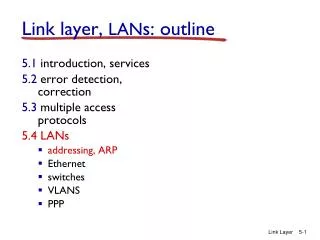
5.1 Introduction and services 5.2 Error detection and correction 5.3Multiple access protocols 5.4 Link-Layer Addressing 5.5 Ethernet 5.6 Link-layer switches 5.7 PPP 5.8 Link virtualization: MPLS 5.9 A day in the life of a web request Link Layer 5: DataLink Layer
MAC Addresses and ARP • 32-bit IP address: • network-layer address • used to get datagram to destination IP subnet • MAC address: • or LAN or physical or Ethernet address • function:get frame from one interface to another physically-connected interface (same network) • 48 bit MAC address (for most LANs) • burned in NIC ROM, also sometimes software settable 5: DataLink Layer
LAN Addresses and ARP Each adapter on LAN has unique LAN address Broadcast address = FF-FF-FF-FF-FF-FF 1A-2F-BB-76-09-AD LAN (wired or wireless) = adapter 71-65-F7-2B-08-53 58-23-D7-FA-20-B0 0C-C4-11-6F-E3-98 5: DataLink Layer
LAN Address (more) • MAC address allocation administered by IEEE • manufacturer buys portion of MAC address space • to assure uniqueness • analogy: (a) MAC address: like Social Security Number (b) IP address: like postal address • MAC flat address ➜ portability • can move LAN card from one LAN to another • IP hierarchical address NOT portable • address depends on IP subnet to which node is attached 5: DataLink Layer
Question: how to determine MAC address of B knowing B’s IP address? ARP: Address Resolution Protocol • Each IP node (host, router) on LAN has ARP table • ARP table: IP/MAC address mappings for some LAN nodes < IP address; MAC address; TTL> • TTL (Time To Live): time after which address mapping will be forgotten • typically 20 min 137.196.7.78 1A-2F-BB-76-09-AD 137.196.7.23 137.196.7.14 LAN 71-65-F7-2B-08-53 58-23-D7-FA-20-B0 0C-C4-11-6F-E3-98 137.196.7.88 5: DataLink Layer
A wants to send datagram to B, and B’s MAC address not in A’s ARP table. A broadcasts ARP query packet, containing B's IP address dest MAC address = FF-FF-FF-FF-FF-FF all machines on LAN receive ARP query B receives ARP packet, replies to A with its (B's) MAC address frame sent to A’s MAC address (unicast) A caches (saves) IP-to-MAC address pair in its ARP table until information becomes old (times out) soft state: information that times out (goes away) unless refreshed ARP is “plug-and-play”: nodes create their ARP tables without intervention from net administrator ARP protocol: Same LAN (network) 5: DataLink Layer
88-B2-2F-54-1A-0F 74-29-9C-E8-FF-55 E6-E9-00-17-BB-4B 222.222.222.221 1A-23-F9-CD-06-9B 111.111.111.111 222.222.222.222 222.222.222.220 111.111.111.110 R 111.111.111.112 49-BD-D2-C7-56-2A CC-49-DE-D0-AB-7D A B Addressing: routing to another LAN walkthrough: send datagram from A to B via R assume A knows B’s IP address • two ARP tables in router R, one for each IP network (LAN) 5: DataLink Layer
88-B2-2F-54-1A-0F 74-29-9C-E8-FF-55 E6-E9-00-17-BB-4B 222.222.222.221 1A-23-F9-CD-06-9B 111.111.111.111 222.222.222.222 222.222.222.220 A B 111.111.111.110 R 111.111.111.112 49-BD-D2-C7-56-2A CC-49-DE-D0-AB-7D • A creates IP datagram with source A, destination B • A uses ARP to get R’s MAC address for 111.111.111.110 • A creates link-layer frame with R's MAC address as dest, frame contains A-to-B IP datagram • A’s NIC sends frame • R’s NIC receives frame • R removes IP datagram from Ethernet frame, sees its destined to B • R uses ARP to get B’s MAC address • R creates frame containing A-to-B IP datagram sends to B 5: DataLink Layer