Versatile FW Bricks
Versatile FW Bricks. Reference +1.5 dBm 54.449-59.146 57.807 x 208 = 12024 59.645-61.618 60.120 x 200 62.542-64.334 62.625 x 192 64.608-66.987 65.347 x 184 67.424-70.409 68.319 x 176 70.524-73.723 71.57 x 168
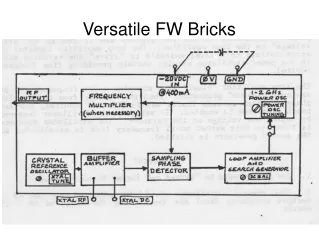

Versatile FW Bricks
E N D
Presentation Transcript
Reference +1.5 dBm 54.449-59.146 57.807 x 208 = 12024 59.645-61.618 60.120 x 200 62.542-64.334 62.625 x 192 64.608-66.987 65.347 x 184 67.424-70.409 68.319 x 176 70.524-73.723 71.57 x 168 74.07 - 77.421 75.15 x 160 77.98 - 81.472 79.105 x 152 82.3 - 85.99 83.50 x 144 87.945-90.9 88.412 x 136 92.69 – 96.69 93.937 x 128 Lock Range – Frequency for 12024
98.748-103.299 100.2 x 120 105.434-110.554 107.357 x 112 113.991-119.031 115.615 x 10⁴ 123.480-129.035 125.25 x 96 +5 dBm Ref 134.841-140.649 136.636 x 88 +8.5 dBm Ref 148.58 150.3 x 80 +10.5 dBm Ref So for this the VCO was running at 3006 MHz for a final multiplication factor of 4 and the references were doubled before the phase detector which works at subharmonics of the VCO frequency. Lock Range – Frequency for 12024
Varying the VCO mechanical tuning for variations on an input reference frequency. 105.001 x 96 10080.092624 1680 x 6 105.001 x 10² 10710.098182 1785 x 6 105.001 x 10⁸ 11340.079786 1890 x 6 108 x 102 11015.960 1836 x 6 107.998 x 96 10367.942 1728 x 6 107.999 x 10⁵ 11339.924 1620 x 7 100.002 x 10² 10200.190 1700 x 6 100.002 x 10⁸ 10800.213 1800 x 6 100.002 x 114 11400.230 1900 x 6 Fixed ref, mult, output, VCO
There are indeed way more possible ranges and variations of the reference frequency than the catalog data suggests. 73, KǾCQ Versatile FW Bricks
Signal Sources 73, KǾCQ
Translation by KØCQ: Watch the location and orientation of the waveguide flanges. The screws set the resonant frequency. There can be leakage at ½ the resonant frequency at a fundamental resonance of the cavities, but the waveguide cutoff frequency prevents any leak through from being a problem. OE0PMJ millimeter wave filters
The wave guide apertures are not an adequate high pass filter. The insertion loss of waveguide below cutoff is not infinite, its more like 10 dB per length equal to the diameter of round guide. And that is at a frequency less than 10% of the cutoff frequency. A high pass filter guide probably should be 8 or ten times longer than its cross section dimension. OE9PMJ millimeter wave filters
In DUBUS 2/2009 DL2AM reported building a scaled OE9PMJ dual cavity for 76GHz. He found he had to enlarge the aperture between the two cavities to get the insertion loss under control. He also found for use and for measuring he had to use isolators before and after the filter. He reported insertion loss when adjusted was 3.4 dB on 76.032 GHz. Part of that was probably the pair of isolators. OE9PMJ millimeter wave filters
Some notes on fabrication. I'm sure the thickness of the web between the two cavities affects the coupling, so if that dimension isn't held tightly, there may be a need to adjust the diameter of that aperture. Same thing for the webs coupling to the waveguides. To keep those under control, drilling the cavities in the center (I'll call it the “cavity plate”) plate the positioning is critical. OE9PMJ millimeter wave filters
If drilling with common 118º drill bits, a pilot hole is crucial because that drill bit grind doesn't cut at the center so tends to run away unless there is a divot wider than the drill bit web thickness. A center drill is very stiff and one good way to mark holes. In England its called a Slocombe bit. A spotting bit is a better solution but harder to find. A 135 degree split point bit cuts to the center and doesn't wander. Its worth the bother of finding because it doesn't need a pilot hole, OE9PMJ millimeter wave filters
Plan to drill the cavity holes undersize. The loss in a cavity resonator depends on the surface resistivity and that is much higher for the rough surface a drill bit leaves behind. It may be practical to use a boring bar in the milling machine to get the holes closer to the design diameter. OE9PMJ millimeter wave filters
After drilling, finish to the final size with an adjustable straight reamer or by sanding to size. To sand to size turn or acquire a dowel, metal rod, or metal tube that just fits in the drilled hole, Preferably with enough clearance for two layers of wet or dry carborundum paper or emery cloth. Cut a slot in the tool lengthwise with a Zona saw or jeweller's saw to take a strip of the carborundum paper or emery cloth. Make the slot longer and the strip wider than the thickness of the cavity plate. Start with about 100 grit, spin with a drill to polish and enlarge the brass to the desired diameter. It may require lengthening the strip to add thickness to reach the desired diameter. Finish with about 400 grit to polish. Much finer is possible these days.. OE9PMJ millimeter wave filters
I'm not sure about the cavity mode used here, but typically in a right circular cylinder the current in the wall is greatest at the end plate. In this design that's not a solid connectioin, but based on pressure between the three plates. If the contact is imperfect the cavity loss will be increased. Silver plating may help, but making sure all four surfaces are truly flat should help. In the extreme one would want the rim of the cavity hole to be a few thousandths of an inch higher than the rest of the cavity plate so that flat cover plates will concentrate the contact pressure at that rim. That's not easy to accomplish. OE9PMJ millimeter wave filters
Flat is easier to accomplish by using the 400 grit carborundum paper supported face up by a flat surface, like a surface plate or plate glass. Wet is handy and it will make the surfaces flatter than the milling machine or factory roll will do. Be careful about dragging fingers on the wet carborundum paper, there's no pain as it takes away flesh. I learned that using that technique to grind quartz crystals eons ago. Valve grinding compound on the flat surface also works but is messier though it won't grind the finger tips. OE9PMJ millimeter wave filters
The plates could be soldered together, but any solder inside the cavity has higher resistance than the brass or copper and its hard to clean out excess solder after the second plate is soldered in place. It might work to tin all four surfaces and while the solder is molten wipe off leaving the thinnest possible layer to do the final bonding. KØCQ OE9PMJ millimeter wave filters
Back about 1964, I struggled to design a low impedance balanced line to match an array. By 1966, my research showed the common formula was incorrect for low impedance lines. So I wrote the article reproduced in the proceedings as it was published in The VHFer. Low impedance parallel transmission lines
This was on page 61 of the April 2010 QST by QST's technical editor
I have to admit only about half the professional references mention the restriction on the simple formula and until March 2017 I found no ARRL resources mention that. Page 20-4 in the ARRL 2014 Radio Handbook is finally correct. Low Z TL
Low Z TL The close spaced formula comes from work of Harold Wheeler about 1939 where he found that the charges on close spaced wires concentrated where the gap was smallest and that affects the computation of the distributed capacitance leading to the inverse cosh formula.
The earliest handbook I had with the full formula dates from 1943, an early edition of the Federal Telephone and Telegraph Radio Handbook. It was copied from a Standard T&T handbook probably printed about 1942. ARRL publications missed the update for about 72 years. Low Z TL
W8JK. Like the LP the adjacent elements are fed out of phase. From Antennas by Kraus 1956. Short LP Feed
The close spaced elements fed out of phase couple tightly and cause considerable circulating current. Short LP Feed
Ben Lowe's K4QF LP feed Short LP Feed
Current in Ben's LP feed at 902 MHz. Not much 8JK effect. Short LP Feed
Ben's feed currents at 1296. 8JK effect visible. Short LP Feed
Ben's feed currents at 2304. No 8JK effect. Short LP Feed
KØCQ's short feed. Short LP Feed
902 Patterns K4QF 6.77 dBi KØCQ 6.77 dBi Short LP Feed