WFC3 Filter Testing, Modeling, Designing
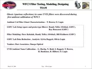
WFC3 Filter Testing, Modeling, Designing. TEAM. Ghosts (spurious reflections) in some UVIS filters were discovered during first ambient calibration of WFC3 Ambient Cal Filter Ghost Characterization – T. Brown, O. Lupie

WFC3 Filter Testing, Modeling, Designing
E N D
Presentation Transcript
WFC3 Filter Testing, Modeling, Designing TEAM Ghosts (spurious reflections) in some UVIS filters were discovered during first ambient calibration of WFC3 Ambient Cal Filter Ghost Characterization – T. Brown, O. Lupie GSFC Lab Setup (spare and proto-type filters): Randy Telfer (Orbital, GSFC), Ray Boucarut (GSFC) Filter Modeling: Dave Kubalak, Randy Telfer, (Orbital), Bill Eichhorn (GSFC) GSFC Lab Data Reduction , Analysis: Sylvia Baggett, Olivia Lupie Vendors: Barr Associates, Omega Optical UVIS Ambient Nano Calibration – G. Hartig, N. Reid, S. Baggett, T. Brown, H. Bushouse, B. Hilbert, O. Lupie
Parameters Used to Spec a Filter to Vendors • Vendor uses specs to design a filter: • Determine substrates, coatings, coating • thicknesses, deposition process. • Provide model of throughput, out of band • rejection, spatial uniformity • Model is accepted or rejected • Vendor builds the filter
Filter Wheel 1 Filter Wheel 6 Filter Wheel 12 UVIS CCD . 57.3 mm 14 mm 10 mm . ~3o . Edge Rays Define Field-Of-View Instantaneous Beam Footprint Image Rays Image WFC3 Filter Testing, Modeling, Designing • Converging instantaneous beam footprint • F31 beam • +/- 3 degree range for field angles WFPC-1’s SOFA – 12 wheels
Modeling Status Possible Model of F225W Ghosting (modelers: Randy Telfer, Dave Kubalak) Aberrations result from reflections from metal blocker Air-Gap Construction Anti-reflection 1 Substrate #1 Substrate 1.1 mm Metal blocker (aberrations –astigmatism) 2 Bond & Spacer GAP (0.38 mm) 3 Shortpass 1 Substrate 3.0 mm Substrate #2 4 Shortpass 2 2nd order ghosts doubly aberrated 1st order ghosts aberrated Ideally – all surfaces perfectly parallel Transmitted Airgap replaced adhesive – adhesive reduced throughput and introduce major spatial dependence across filter
Flight Filter Ghosts (worst cases) <1% in white light > 10% in white light > 10% in white light F218W F225W F300X F218W F225W <1% in white light F606X (analysis T. Brown with ICAL team) Some wide band UV air-gap filters exhibited large amplitude ghost images:
0.02% 0.3% 0.06% 0.08% test artifact 0.08% 0.13% Lab Measurements of Spare F606 Flight – F606W in WFC3 White light – 5 micron fiber Spare – F606W – lab Cohu, 10 micron fiber Xenon Lamp Faint point ghosts at ~0.1% of the primary image intensity, moving little with field position. Larger donut ghosts at 0.3%, moving significantly. Faint point ghosts at ~0.01% of the primary image Intensity. Field angle check in work.. *white light ghosts 10x fainter than Flight – however more testing is needed to verify.
F225W Primary images ghosts 200 nm 275 nm Low level ghosts 400 nm 1100 nm
Spectral Modeling of Ghosts (D. Kubalak) Ghost spectral modeling- D. Kubalak
Phase Retrieval and Spectral Ghost Models Flight Filter Strange Morphology combination of Astigmatism, overall curvature, local surface ripples Phase Retrieval from Focus Sweeps (R. Telfer)
Air-Gap Ghost Mechanisms Two-surface reflection modeling indicates the metal blocker is the likely origin of the ghost behavior. Vendors also say that the metal coating is the least “controllable”. The observed wavelength dependence is understood. Red and Blue near-band wings are not as steep as desired. This excess light occurs at the wavelengths where ghosts could be produced by the air-gap construction. Model ghost fluxes (10-12%) are comparable to measured in white light. Phase Retrieval reveals ghost images are astigmatic for 218W and 225W, that the coatings are tilted w/r to one another, and filter has a slow, slight curvature possibly consistent with a shrinkage/distortion at the spacer/metal blocker interface. None of these issues have any effect on the transmitted beam and throughput – both wereexcellent.
Status Filter-Ghost Mitigation Plan PLAN STATUS • Adopt a 3-option approach for Air-Gaps: • Barr to proto-type new F218, 225, (and 300X) filters – single substrate • IPT tested image quality using special lab setup – flight • Spare filters to see if they exhibit less ghosting. • IPT is investigating a wedge fix – original design but • with increased wedge to deflect reflected light; • IPT is investigating dual-wheel air gap – achieved • wedge by stacked-SOFA wheel approach; • requires two coated substrates and loss of a filter(s). • 2. Mechanism for F606w (laminated) ghosts • is being discussed with OMEGA. Barr sent thin prototype single substrate – testing in the GSFC – only one ghost present, white light 0.6% F218 and F225 spares same problem. F606 spare exhibits similar type ghosts but greatly reduced ghost amplitude (~0.03%) Modeling shows you cannot tilt filter enough and still stay with bounds of the filter housing.. By “tilting” the spare air-gap, we can determine how much relative tilt of the two substrates is needed to move the ghosts out of the fov. Data taken last night. OMEGA is devising a new design.
O f f - a x i s P a r a b o l a • UV Sensitive CCD. • Cover Structure for uniform/dark background. • Mechanical stage mount for filters. • Automated Castle and • CCD data take system. • Semi-Automated data • reduction and analysis. F i b e r C C D F i l t e r F / 3 1 B e a m Castle Cart Double Mono chrometer GSFC Lab Testing Facility Optics Team: R. Telfer, R. Boucarut, D. Kubalak, B. Eichhorn, J. Kirk, B. Greeley Science IPT: O. Lupie, S. Baggett, B. Hilbert, T. Brown, G. Hartig Goals – last few weeks: 1) Prove that the GSFC Lab Test setup accurately simulates the WFC3, i.e., measurements are true representations of the filter imaging quality, and 2) Measure the flight spares. presents F31 light beam to the filters as they would see in the WFC3+OTA
Lab Measurements of Spare F225W SPARE F225 Cohu Video CCD, 200 micron fiber SPARE F225 SBIG CCD,10 micron fiber, FLIGHT F225 5 micron fiber, WFC3 Saturated prime Saturated prime (sum ghosts=15%) 10% 0.5% 9% 2% 0.5% 10% UV00 Saturated prime UV00 UV14 Relative positions and fluxes of ghosts in the spares are comparable to those in the flight similar mechanisms. UV14 Note – rotation and stretch are different.
Example Monochromatic Results for Spare F225W Spare F225, SBIG-CCD, 200 micron fiber, 13nm bandpass, double UVIS, , with ND1 (removed in later imaging). 220nm 280nm 240nm 260nm 300 nm 320 nm 340 nm Figure from S.Baggett
Establish Setup Sensitivity and Repeatability Spare F225W Ran many tests to establish sensitivity to ghosts, setup alignment accuracy, and experimented with several different filter orientations: rotation, back to front, tilts, translation, wedge orientation and detector tilts. nominal -1d -2d +1d +2d Xenon Lamp, 10 mic Fiber Rotate Filter a few degrees from nominal and compare Ghost morphology
Establish Setup Sensitivity and Repeatability Also Helps modelers to see all the ghosts saturated unsaturated saturated unsaturated Primary, Secondary ghosts emerge from behind the primary and each other when large translations or rotations of the filter are introduced: ie different locations on filter and differing field angles. center center - shows repeatability +0.5 in +1.0 in -0.5 in -1.0 in Xenon Lamp, 10 mic Fiber v. Large tilt – 30 deg to corner Translating the filter Figure from S.Baggett
nominal -3d -6d -12d -15d -9d Prototype Single Substrate – large tilts (Xenon Lamp, 10 micron fiber, CCD SBIG) Prototype F225 – Single Substrate Setup artifact Prototype thickness is smaller than that of a flight filter. Thicker filters result in ghosts at a larger radial distance from the primary. But tilting the thin filter, we can see when the ghost emerges and use a simple Model to derive the ghost position with a thicker filter. Ghost 0.6% Figure from S.Baggett
Proto Type F225 From Barr
Setup artifact 200nm 225nm 300nm 250nm Ghost#1 Ghost#2 350nm 450nm 500nm 400nm 600nm 700nm 650nm 750nm 850nm 900nm 900nm 800nm Prototype F225 – Single Substrate Ghosts as a function of wavelength Setup SBIG CCD, 200 mic fiber Castle Modes <250nm double UV 250-310 double UVIS 310-760 double VIS >760 double IR Figure from S.Baggett
53 of 63 filters exhibit excellent performance, consistent with spec. • 47 filters < 0.2% ghosts • 6 filters 0.2-0.5% ghosts • - multi-substrate - 410M, 689M, 814M • - air-gap – 656N, 665N, 673N • 2 filters 0.7% ghosts: • single substrate+Al blocker - 275W can calibrate • air-gap - 658N • 2 UV high priority air-gap (with Aluminum blocker) 10-15%ghosts - 218W, 225W unsuitable for flight • 1 UV air-gap 1% with strange morphology - 300X marginal, tough to calibrate • 1 3-substr laminated, < 0.5% “point-like” ghosts - 606W most used filter, concern • (other filters with very low level “point ghosts”: 625W, 775W, 410M, 467M, 547M, 621M, 689M) • 1 UV single subst.+Al block, possible surface flaw – 280N serious but low priority filter • 2 UV Quad filters single substrate, 5% ghosts:– 232N, 243N low priority filters, can calibrate • Grism – data reduction in work