Geo-localisation in CERN’s underground facilities
20 likes | 258 Views
Fq C+D from TBS2/OMU 6. IT. Beam Line. LHC4. Geo- localisation in CERN’s underground facilities. CERN. TBS 2 TRX C TRX D. Indoor Repeater. Indoor Repeater. OMU 2. IT. Repeater. Geo-localisation in CERN’s underground facilities. Outdoor Repeater. Concrete Wall. OMU 4.

Geo-localisation in CERN’s underground facilities
E N D
Presentation Transcript
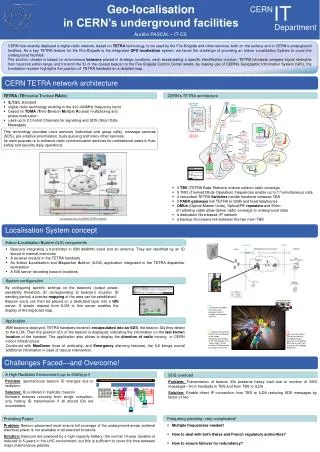
FqC+D from TBS2/OMU 6 IT Beam Line LHC4 Geo-localisation in CERN’s underground facilities CERN TBS 2 TRX C TRX D Indoor Repeater Indoor Repeater OMU 2 IT Repeater Geo-localisation in CERN’s underground facilities Outdoor Repeater Concrete Wall OMU 4 Fq A+B and Fq C+D to repeaters OMU 6 OMU 1 Ethernet/USB converters LHC5 Ethernet/USB converters ~ AC 230V Repeater LHC3 FqC+D to Core OMU 3 Indoor Repeater UTP cabling : ~100m Backup Microwave link Department Core TBS 3 TRX E BA80 LHC2 Indoor Repeater SPS2 FqA+B from TBS1/OMU 5 Indoor Repeater Aurélie PASCAL – IT-CS Indoor Repeater Indoor Repeater OMU 7 Indoor Repeater ~ AC 230V SPS3 Outdoor Repeater Indoor Repeater Fq E to outdoor repeaters SPS1 Beacons Antennas USB Hub Indoor Repeater Indoor Repeater SPS4 LHC6 USB cables CERN has recently deployed a digital radio network, based on TETRA technology, to be used by the Fire Brigade and other services, both on the surface and in CERN’s underground facilities. As a key TETRA feature for the Fire Brigade is the integrated GPS localisation system, we faced the challenge of providing an Indoor Localisation System to cover the underground facilities. The solution chosen is based on autonomous beacons placed in strategic locations, each broadcasting a specific identification number. TETRA handsets compare signal strengths from beacons within range and transmit the ID of the closest beacon to the Fire Brigade Control Center where, by making use of CERN’s Geographic Information System (GIS), the localisation system highlights the position of TETRA handsets on a detailed map. Indoor Repeater SPS7 Electrical boxes enablingremote reboot Indoor Repeater SPS5 SDI2 LHC1 Indoor Repeater Laptop running beacons configuration tool Indoor Repeater Outdoor Repeater Indoor Repeater Indoor Repeater LHC7 TBS 1 TRX A TRX B Outdoor Repeater PS/Booster Legend: OMU 5 Indoor Repeater Radiatingcable Terminal Server Optical fiberlink LHC8 LINAC4 RF link FqA+B to Core CERN TETRA network architecture • TETRA (TErrestrialTrunkedRAdio) • E.T.S.I. standard • digital radio technology working in the 410-430MHz frequency band • based on TDMA (Time Division Multiple Access) multiplexing and • phase modulation • uses up to 2 Control Channels for signalling and SDS (Short Data • Messages) • This technology provides voice services (individual and group calls), message services (SDS), pre-emptive prioritisation, busy queuing and many other services. • Its main purpose is to enhance radio communication services for professional users in their safety and security daily operations. • CERN’sTETRA architecture • 3 TBS (TETRA Base Stations) ensure outdoor radio coverage • 5 TMO (Trunked Mode Operation) frequencies enable up to 17 simultaneous calls • 2 redundant TETRA Switches handle handover between TBS • 2 PABX gateways link TETRA to GSM and fixed telephones • OMUs (Optical Master Units), Optical/RF repeaters and 50km • of radiating cable allow deliver radio coverage to underground sites • a dedicated, fibre-based, IP network • a backup microwave link between the two main TBS Conceptualview of CERN’s TETRA network Localisation System concept • Indoor Localisation System (ILS) components • Beacons integrating a transmitter in ISM 868MHz band and an antenna. They are identified by an ID stored in internal memories • A receiver module in the TETRA handsets • An Indoor Localisation and Dispatcher Add-on (ILDA) application integrated in the TETRA dispatcher workstation • A GIS server recording beacon locations • System configuration • Application • With beacons deployed, TETRA handsets transmit, encapsulated into an SDS, the beacon IDs they detect to the ILDA. Then the position (ID) of the beacon is displayed, indicating the information on the last known location of the handset. The application also allows to display the direction of radio moving in CERN indoor infrastructure. • Combined with ManDown (lose of verticality) and Emergency alarming features, the ILS brings crucial additional information in case of rescue intervention. FirebrigadeOperator By configuring specific settings on the beacons (output power, sensibility threshold, ID corresponding to beacon’s location, ID sending period) a precise mapping of the area can be established. Beacon icons can then be placed on a dedicated layer into a GIS server. A simple request from ILDA to this server enables the display of the expected map. 1. Beaconslocated in the tunnel eachbroadcasttheir ID throughan integratedantenna 2 3 1 2. Handsetsforward the ID of the nearestbeacon to the Indoor Geolocalisation Display at the Fire Brigade (via a "leaky feeder " whichprovides GSM and radio coverage in the tunnel) 3. In case of incident (lossof verticalityor emergency buttonpressed) an emergency SDS and an alarm are sent to the Fire Brigade Dispatcher Challenges Faced—and Overcome! • A High Radiation Environment (up to 600Gy/yr!) • Problem: spontaneous beacon ID changes due to radiation. • Solution: ID is stored in triplicate; beacon • firmware ensures recovery from single corruption, only halting ID transmission if all stored IDs are inconsistent. SDS overload Problem: Transmission of beaconIDspresentsheavyload due to number of SDS messages---fromhandsets to TBS and from TBS to ILDA Solution:Enable direct IP connectionfrom TBS to ILDA reducing SDS messages by factor of two • Frequency planning: verycomplicated! • Multiple frequenciesneeded! • How to deal with both Swiss and French regulatory authorities? • How to ensure failover for redundancy? • Providing Power • Problem: Beacon placement must ensure full coverage of the underground areas; externalelectrical power is not available in all selected locations. • Solution:Beacons are powered by a high-capacitybattery; the normal 10-year duration isreduced to 5-years in the LHC environment, but thisissufficient to cover the time between major maintenance periods.