Download
1 / 55
640 likes | 977 Views
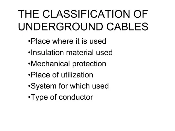
UNDERGROUND CABLES part 2. Electrical Characteristics of Cables. Electric Stress in Single-Core Cables p. 408 Capacitance of Single Core Cables p.433 Charging Current Insulation Resistance of Single- Core Cables p.431 Dielectric Power Factor & Dielectric Losses p.442

E N D
Electrical Characteristics of Cables • Electric Stress in Single-Core Cables p. 408 • Capacitance of Single Core Cables p.433 • Charging Current • Insulation Resistance of Single- Core Cables p.431 • Dielectric Power Factor & Dielectric Losses p.442 • Heating of Cables: Core loss ; Dielectric loss and intersheath loss p.441
Electric Stress in Single-Core Cables p. 408 D= q/(2πx) E = D/ε = q/(2πεx) q: Charge on conductor surface (C/m) D: Electric flux density at a radius x (C/m2) E: Electric field (potential gradient), or electric stress, or dielectric stress. ε: Permittivity (ε= ε0. εr) εr: relative permittivity or dielectric constant.
r: conductor radius. R: Outside radius of insulation or inside radius of sheath. V: potential difference between conductor and sheath (Operating voltage of cable). Dielectric Strength: Maximum voltage that dielectric can withstand before it breakdown. Average Stress: Is the amount of voltage across the insulation material divided by the thickness of the insulator.
Emax = E at x = r = V/(r.lnR/r) Emin = E at x = R = V/(R.lnR/r) For a given V and R, there is a conductor radius that gives the minimum stress at the conductor surface. In order to get the smallest value of Emax: dEmax/dr =0.0 ln(R/r)=1 R/r=e=2.718
Insulation thickness is: R-r = 1.718 r Emax = V/r (as: ln(R/r)=1) Where r is the optimum conductor radius that satisfies (R/r=2.718)
Example A single- core conductor cable of 5 km long has a conductor diameter of 2cm and an inside diameter of sheath 5 cm. The cable is used at 24.9 kV and 50 Hz. Calculate the following: a- Maximum and minimum values of electric stress. b- Optimum value of conductor radius that results in smallest value of maximum stress.
a- Emax = V/(r.lnR/r) = 27.17 kV/cm Emin = V/(R.lnR/r) = 10.87 kV/cm b- Optimum conductor radius r is: R/r = 2.718 r= R/2.718= 0.92 cm The minimum value of Emax: = V/r = 24.9/0.92=27.07 kV/cm
Grading of Cables p.414 Grading of cables means the distribution of dielectric stress such that the difference between the maximum and minimum electric stress is reduced. Therefore, the cable of the same size could be operated at higher voltages or for the same operating voltage, a cable of relatively small size could be used.
1. Capacitance Grading p.414 This method involves the use of two or more layers of dielectrics having different permittivities, those with higher permittivity being near the conductor. Ex =q/(2 πεo.εr .x) The permittivity can be varied with radius x such that (ideal case): εr = k/x Then Ex =q/(2 πεo. k) Ex is constant throughout the thickness of insulation.
r < r1 < r2 ε1 > ε2 > ε3 r1 r2 R r ε1 ε2 ε3
In the figure shown At x=r Emax1 =q/(2 πεo. ε1r) At x=r1 Emax2 =q/(2 πεo. ε2r1) At x=r2 Emax3 =q/(2 πεo. ε3r2) If all the three dielectrics are operated at the same maximum electric stress (Emax1=Emax2=Emax3=Emax) , then: (1/ ε1r) = (1/ ε2r1) = (1/ ε3r2) ε1r = ε2r1 = ε3r2, get r1 , r2
2. Intersheath Grading p.419 r1 ε ε r2 ε r V V1 V2 R V=0
Intersheath Grading is a method of creating uniform voltage gradient across the insulation by means of separating the insulation into two or more layers by thin conductive strips. These strips are kept at different voltage levels through the secondary of a transformer.
In this method only one dielectric is used but the dielectric is separated into two or more layers by thin metallic intersheaths. Emax1 = (V-V1)/(r. ln(r1/r)) Emax2 = (V1 –V2)/(r1. ln(r2/r1)) Emax3 = V2/(r2.ln(R/r2)) For the same maximum electric strength: (r1/r) =(r2/r1) =(R/r2) = α R/r = α3 Then: (V-V1)/(r.ln α) =(V1-V2)/(r1.ln α)=(V2/r2.ln α) (V-V1)/r =(V1-V2)/r1= V2/r2
If the cable does not have any intersheath, the maximum stress is: Emax = V/(r.ln(R/r)) = V/(3r.ln α) The intersheath radius can be found from R/r = α 3 (r1/r) =(r2/r1) =(R/r2) = α The voltages V1, V2 can be found from: (V-V1)/r =(V1-V2)/r1= V2/r2 Emax /Emaxwithout intersheath =3/(1+ α + α 2) where ===α > 1
Difficulties of Grading a-Capacitance grading : 1- non-availability of materials with widely varying permittivities. 2- The permittivities of materials will be change with time, so the electric field distribution may change and lead to insulation breakdown.
b- Intersheath Grading 1- Damage of intersheaths during laying operation. 2- The charging current that flows through the intersheath for long cables result in overheating. 3- The setting of proper voltages of intersheaths.
Example A single core cable for 53.8 kV has a conductor of 2cm diameter and sheath of inside diameter 5.3 cm. It is required to have two intersheaths so that stress varies between the same maximum and minimum values in three layers of dielectric. Find the positions of intersheaths, maximum and minimum stress and voltages on the intersheaths. Also, find the maximum and minimum stress if the intersheaths are not used.
R/r = a3 a= 1.384 (r1/r) =(r2/r1) =(R/r2) = a r1= 1.384 cm, r2= 1.951 cm (V-V1)/(r.lna) =(V1-V2)/(r1.lna)=(V2/r2.lna) (V-V1)/(1.lna) =(V1-V2)/(1.384.lna) =(V2/1.915.lna)
V= 53.8 kV V1= 41.3 kV, V2=23.94 kV Emax = (V-V1)/(r. lna)=38.46 kV/cm Emin = (V-V1)/(r1. lna)= 27.79 kV/cm If Intersheaths are not used: Emax = V/(r.ln(R/r)) = 55.2 kV/cm Emin = V/(R.ln(R/r)) = 20.83 kV/cm
Example Find the maximum working voltage of a single core cable having two insulating materials A and B and the following data. conductor radius 0.5 cm, inside sheath radius 2.5cm. The maximum working stress of A 60 kV/cm, maximum working stress of B 50 kV/cm, relative permittivities of A and B, 4 and 2.5 respectively.
60=(q/2πεo. εAr) q/(2πεo)=120 50=(q/2πεo. εBr1) = 120/(2.5 r1) r1= 0.96 cm V=q.ln(r1/r)/(2πεo. εA) + q.ln(R/r1)/(2πεo. εB) =(120/4). ln(0.96/0.5) +(120/2.5). ln(2.5/0.96) = 65.51 kV
Electrical Characteristics of Cables • Electric Stress in Single-Core Cables p. 408 • Capacitance of Single Core Cables p.433 • Charging Current • Insulation Resistance of Single- Core Cables p.431 • Dielectric Power Factor & Dielectric Losses p.442 • Heating of Cables: Core loss ; Dielectric loss and intersheath loss p.441
Capacitance of Single Core Cables p.433 Assume that the potential difference between conductor an sheath is V, then a charge of conductor and sheath will be +q and –q (C/m) C= q/V C= 2 πε/ln(R/r) F/m
Since ε = ε0 . εr C = 2πε0. εr /ln(R/r) F/m Where: ε0= 8.854x10⁻¹² εr dielectric constant of insulation. C= 10-9εr/(18.ln(R/r)) F/m C= εr/(18.ln(R/r)) μF/km
Charging Current Ich = V/Xc = ω.C.V = 2πf.C.V It is observed that as cable length and operating voltage increase, Capacitance (c) and the charging current will be increase. So, it is not recommended to transmit power for a long distance using underground cables (Overvoltage problems)
SinceC= 2 πε/ln(R/r) andIch = ω.C.V The charging current and the capacitance are relatively greater for insulated cables than in O.H.T Lines because of closer spacing and the higher dielectric constant of the insulation of the cables. The charging current is negligible for O.H circuits at distribution voltage (Short Lines).
Where: Ri : insulation resistance in ohms. ρ: insulation (dielectric) resistivity in Ω.m l: Cable length (m). It is observed that the insulation resistance is inversely proportional to the cable length.
Dielectric Power Factor and Dielectric Losses p.442 When a voltage is applied across a perfect dielectric, there is no dielectric loss because the capacitor current Ic is at 90o ahead of the voltage V. In practice, there is a small current component Id (leakage current) that in phase with voltage V, so, the total current I leads the voltage V by an angle less than 90 as shown in figure.
Id Id
Power factor of dielectric : = Cos фd = Cos (90-δ) = Sin δ This provides a useful measure of the quality of the cable dielectric.
For a good dielectric insulation, фd is close to 90o. Pd =I. V. Cosфd Cos фd = Sinδ = tan δ = δ (rad) δ is called dielectric loss angle. The dielectric Losses: Pd Pd = Id.V = Ic.tanδ.V = Ic.V.δ ==Ic = ωCV Pd = ωCV2δδ is in radians C: Cable capacitance. V: operating voltage
Since δ = 90- фd and δ < 0.5o for most cables. Here Cos фd should be very small under all operating conditions. If it is large, the power loss is large and the insulation temperature rises. The rise in temperature causes a rise in power loss in the dielectric which again results in additional temperature rise. If the temperature continues to increase, the cable insulation will be damaged.
Example A single-core cable has a conductor diameter of 2 cm, inside diameter of sheath is 6 cm and a length of 6 km. The cable is operated at 60 Hz and 7.2 kV. The dielectric constant is 3.5, the dielectric power factor is 0.03 (δ=Cosфd) and dielectric resistivity of the insulation is 1.3x10⁷ MΩ.cm.
Calculate the following: a- Maximum electric stress. b- Capacitance of the cable. c- Charging current. d- Insulation resistance. e- Total dielectric losses. f- If the cable feeds a load at receiving end of 20A at 0.6 power factor lag, find sending end current and power factor.
Solution a- Emax = V/(r.ln(R/r)) = 6.55 kV/cm b- C= k/(18.ln(R/r)) μF/km = 0.176x6 = 1.0619 μF c- Ich = V/Xc = ω.C.V = 2.88 A d- Ri =ρ.ln(R/r)/(2πl) = 3.79 MΩ e- Pd = Ich.V.Cos фd =622 W
f- load current: I= 20 ( Cosф – j sinф) =12 - j16 Ich= j2.88 Is= I + Ich =12- j13.12 = 17.78 A фs = 47.55o Cos фs = 0.67 lag
Measurement of Capacitance of 3-core Cables p.436 Cy = Cs + 2 Cc