Download
1 / 15
150 likes | 276 Views
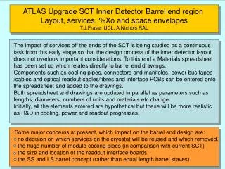
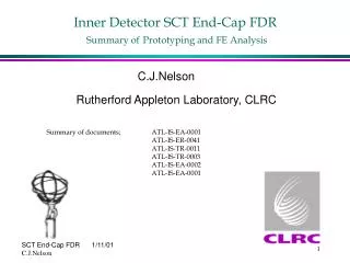
Inner Detector SCT End-Cap FDR Summary of Prototyping and FE Analysis. C.J.Nelson. Summary of documents; ATL-IS-EA-0001 ATL-IS-ER-0041 ATL-IS-TR-0011 ATL-IS-TR-0003 ATL-IS-EA-0002 ATL-IS-EA-0001. Rutherford Appleton Laboratory, CLRC.

E N D
Inner Detector SCT End-Cap FDRSummary ofPrototyping and FE Analysis • C.J.Nelson Summary of documents; ATL-IS-EA-0001 ATL-IS-ER-0041 ATL-IS-TR-0011 ATL-IS-TR-0003 ATL-IS-EA-0002 ATL-IS-EA-0001 Rutherford Appleton Laboratory, CLRC
Prototyping and FE AnalysisSample tests • Skin laminate: Tensile Good result E=112 GpaStrength = 400 MPa • Sandwich FWT Good result 2.5 - 3.9 MPa • 4 Point Bend : Good correlation
Prototyping and FE AnalysisPrototype Wing Inspection of wing Frq test: Expt. Set-up
Prototyping and FE AnalysisPrototype Wing/ Modal Correlation
Prototyping and FE AnalysisStructure FE Modelling • ANSYS FEA • -Shell 91 composite elements, 3 layers, ‘thick’ sandwich Early Model ~2500 elements -Coarse mesh -discs attached to cylinder -mass only 100 kg Max defl ~0.12mm Nat freq ~8 Hz
Prototyping and FE AnalysisFEA :Detailed model Detailed Model ~37 000 elements -Fine mesh where reqd. -accurate apertures -cylinder flanges -12 point disc attachment -Mass 168 kg Max defl ~0.5 mm Nat freq ~6.4 Hz
Prototyping and FE AnalysisFEA :Detailed model Detail of mesh at disc mounting positions
Prototyping and FE AnalysisModel constraints • Fixed (spatially as per plot) • Front Wing: Y, Z-rotation • Front Wing: X, Y, • Z-rotation • Rear wing: Z,Y , X-rotation • Y-rotation and Z-rotation • Rear wing: all 6 dofs Model showing constraints under wing tips
Prototyping and FE AnalysisLoad Case 1: Initial conditions -Deflection Predicted vector deflections (mm) Vertical deflections (mm) under gravity and operating temperatures
Prototyping and FE Analysis Load Case 1: Initial conditions -Stresses
Prototyping and FE Analysis Load Case 2: Initial conditions including worst case CME;
Prototyping and FE Analysis Load Case 3: Temperature Variation Conditions Upper half of cylinder : 5 deg above expected All discs : 5 deg above expected Results
Prototyping and FE Analysis Modal Analysis Very similar modes to early model, but with extra mode for ITE
Prototyping and FE Analysis Random Analysis Results from psd analysis of early model
Prototyping and FE Analysis Conclusions • Tests have been done to confirm material properties and modelling • Prototyping has proved manufacturability of proposed sandwich with Korex • Detailed model confirmed early results • Predicted deflections, stresses are acceptable • Structure is fit for purpose!