Download
1 / 1
10 likes | 153 Views
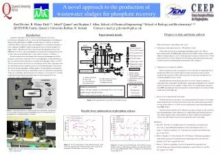
Sludge settled: Wastewater low in phosphate separated from P-rich sludge. Phosphate. Remaining phosphate taken up by cells for growth and to reform polyphosphate. pH control. to P.C . Key. Acid. A. Alkali. Gas flow regulator. Datalogger. Dlg. 2/2 way Gas solenoid. Dlg. ANAEROBIC.

E N D
Sludge settled: Wastewater low in phosphate separated from P-rich sludge Phosphate Remaining phosphate taken up by cells for growth and to reform polyphosphate pH control to P.C. Key Acid A Alkali Gas flow regulator Datalogger Dlg 2/2 way Gas solenoid Dlg ANAEROBIC AEROBIC Dlg To contacts Dlg 3/2 way pinch valves Influent wastewater containing phosphate mixed with EBPR sludge T P-rich sludge Dlg Datalogger contacts 1 Peristaltic pump 4 F E Anaerobic release of phosphate by cells Digital timer switch Filled volume 5.5 L Phosphate Temperature sensor T Polyphosphate 2 One way gas valve D 3 Inputs/Outputs Air Addition of calcium as a precipitant 5 Drawn volume 2.25 L 1. Influent media 2.. Sludge samples/ mixed liquor removal 3. Supernatant removal 4. Effluent gas 5. Influent air /nitrogen N2 C Chemistry of the solution around cells favours precipitation A = Mixer and stirrer B = Gas trap C = Gas distributor D = 9 litre vessel E = pH/ conductivity meter F = Level controller G = Media reservoir 8hr ‘Fill and Draw’ cycle; 2hr Anaerobic, 4.5hr Aerobic, 1.5hr Settlement Synthetic wastewater feed Glucose 165 mg/L, Sodium acetate 200 mg/L,Yeast extract 75 mg/L, K2 HPO4 98mg/L, KH2 PO4 56 mg/L, Minimal media and Trace elements (Kuba et al 1993) A novel approach to the production of wastewater sludges for phosphate recovery Paul Devine, R. Elaine Dick**, John P. Quinn* and Stephen J. Allen, School of Chemical Engineering/ *School of Biology and Biochemistry/ ** QUESTOR Centre, Queen’s University Belfast, N. Ireland Contact e-mail; p.g.devine@qub.ac.uk Introduction • Progress to date and future outlook • Work on this project is proceeding in three stages; • Optimisation of phosphate release in a ‘Fill and Draw’ system • Work to date has focused on optimising the phosphate release in the ‘fill and draw’system seeded with EBPR sludge from Severn Trent Water sewage treatment works (Milcote), England (Figures 2 and 3). Stable phosphate cycling was achieved over a 30 day period with releases of up to 30mg/l P above the influent achieved during operation with synthetic wastewater containing high concentrations of PO4. (Figure 4) • Optimisation of crystallisation conditions • Batch crystallisation studies are in progress to assess the effect of biologically driven precipitation on PO4 release and precipitant calcium concentrations under anaerobic conditions.Data from these studies will form the basis for the design and operation of a continious phosphate recovery system. • Should biologically driven precipitation prove successful, sludge containing two independent forms of phosphate, polyphosphate and precipitated phosphate salts, would be formed. The potential exists to produce a sludge with 9% P as polyphosphate (internally) from EBPR and additional surface precipitated crystalline phosphate, the amount of which would increase with sludge age. • Recovery of crystalline product from sludge • The direction that this stage takes is very much dependent on the quality of crystalline sludges produced after strand two. Research has shown that sludge incineration followed by water elution (Matsuo et al 1996) can extract biologically sequestered polyphosphate from EBPR sludges. • Thermal treatment could be used to eliminate the organics leaving ash with a relatively high calcium phosphate content although costs would be high and a further purification step could be required. Other suitable methods are likely to depend on the phosphorus content achievable and the concentration of undesirable metals in the sludge. Experimental details A number of phosphate recovery processes based upon the side-stream crystallisation of phosphate salts (e.g. struvite and calcium phosphate) from Enhanced Biological Phosphate Removal (EBPR) anaerobic liquor are currently in operation world-wide. We are in the early stages of development of a novel main-stream process for the adaptation of EBPR to induce the precipitation of recoverable phosphates on sludge surfaces. This process involves using the anaerobic phosphate release in the EBPR process to drive a surface precipitation reaction that may be hindered by the lack of super-saturation of phosphate ions in conventional wastewaters (see Figure 1). Previous work on heavy metal removal has shown that the manipulation of local phosphate concentrations around the surfaces of polyphosphate-accumulating bacteria may be used to initiate the formation of crystalline metal phosphates (Dick et al 1995). The cell surface provides the foci for crystal formation and the efflux of phosphate from the cells during anaerobic conditions results in a locally high phosphate concentration that exceeds the metal phosphate solubility product. Once precipitates have formed on the cells crystal growth and metal and phosphate removal is rapid.Surface precipitation of this type is intended to provide the basis for a multi-pass recovery process eventually combining efficient biological phosphate removal with the production of non-voluminous sludges with high P content. Figure 3. The experimental set-up of the ‘fill and draw’system. Results from optimisation of phosphate release Figure 1. The proposed process of biologically driven phosphate precipitation in bio-p sludges.Using the anaerobic phosphate release we intend to drive the precipitation of calcium phosphate or struvite. • References • Dick, R.E., Boswell, C.D. and Macaskie,L.E., Uranyl phosphate accumulation by Acinetobacter spp. In Biohydromettalurgical Processing Volume II. Jerez, C.A., Vargas, T., Toledo, H. and Wiertz, J.V., (eds) Yniversity of Chile, Viña del Mar, Chile pp. 177-186 (1995) • Kuba, T., Smolders, G. Van Loosdrecht, M. C. M., Heijnen, J.J.Biological phosphorus removal from wastewater by anaerobic-anoxic sequencing batch reactor. Water Sci. and Tech. Vol. 27 No. 5-6 pp 241-251(1993) • Matsuo, Y., Release of phosphorus from fly ash produced by incinerating waste activated sludge from enhanced biological phosphorus removal. Water Sci. and Tech Vol 34, pp407-415. (1996) Figure 4. Levels of phosphorus in the influent medium, at the end of the anaerobic and aerobic periods of the second of the three daily ‘Fill and Draw’ cycles over 30 days. Figure 5. Cod removal and MLSS in the ‘Fill and Draw’reactor during 30 days of stable operation.Earlier runs showed a fall off in P-cycling at MLSS above 3500, so sludge was wasted when it reached this level. Figure 2 the lab-scale ‘fill and draw’ set-up used in phosphate release experiments