Download
1 / 43
480 likes | 825 Views
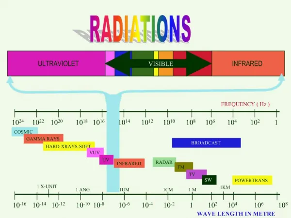
Electro-Magnetic Infrared RAdiation. Infrared Beamline (EMIRA) at SESAME Current Status and New Updates. Ibraheem YOUSEF SESAME Synchrotron ibraheem.yousef@sesame.org.jo. Outlines. Simulation and Design of the Infrared Beamline at SESAME a) The Infrared Source Characteristics for SESAME

E N D
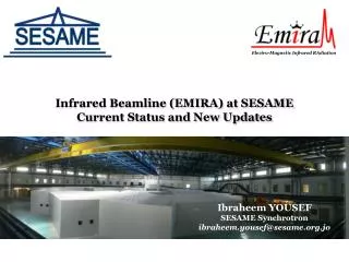
Electro-Magnetic Infrared RAdiation Infrared Beamline (EMIRA) at SESAMECurrent Status and New Updates Ibraheem YOUSEF SESAME Synchrotron ibraheem.yousef@sesame.org.jo
Outlines • Simulation and Design of the Infrared Beamline at SESAME a)The Infrared Source Characteristics for SESAME b) Optical Design Simulation c) Beamline Design d) Experimental Station • The Progress in the IR beamline since the last SAC
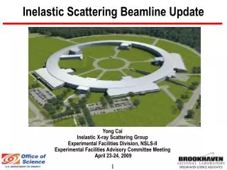
SESAME Storage Ring Parameters • IR beamline will be one of the three Day-1 beamline at SESAME • IR beamline will be the first one fully designed at SESAME
Collection and Design Details • Infrared light will be collected from (ER +BM sources) • Vertical collection angle = 15 mrad • Horizontal collection angle = 39 mrad • Collection geometry optimized using SRW and Rays Tracing
Initial Wavefront Profile Center of aperture (optical axis) 11 mrad Straight section axis 10 microns (Mid-IR ) 15 mrad 15 mrad 39 mrad 100 microns (Far-IR)
Comparison with SOLEIL and other Synchrotrons Note: SOLEIL (black) 78mrad (H) x 20mrad (V); 500mA, DIAMOND (blue) and Australian Synchrotron (green).
Simulation and Design of the Infrared Beamline at SESAME a)The Infrared Source Characteristics for SESAME b) Optical Design Simulation c) Beamline Design d) Experimental Station • The Progress in the IR beamline since the last SAC
Space and optimized distances Tunnel wall BendingMagnet Side VIEW TOP VIEW
M3 Flat Optical Layout Tunnel wall M4 Flat Source Diamond window M7 A Flat Branch 1 Cylindrical mirror (VFM) M1 Flat M2 Toroid Cylindrical mirrors (HFM) M8 A Parabolic M7 B Flat Branch 2 Spectrometer 1 M8 B Parabolic Spectrometer 2 Schematic layout of optical path from the source inside the tunnel wall until the instruments
Optical Layout after the first focus M4 Flat Diamond window M7 A Flat Cylindrical mirror (VFM) Branch 1 Cylindrical mirrors (HFM) M8 A Parabolic M7 B Flat Branch 2 Spectrometer 1 M8 B Parabolic Spectrometer 2
Beam Profile simulation Branch 1 Branch 2 (20x30)mm² Profile at 8.7 m Profile at 8.7 m (20x30)mm² Profile at 11.7 m Profile at 11.7 m
Heat load at first mirror: solution= slotted M1 Calculated power density on the same mirror Initial wavefront distribution of the 10 mm wavelength on first mirror
Heatload on first mirror (zoom) @ 2.05 meterfromsource
Proposed solution: A slot of 4 mm total (1.95 mrad) Flux At slotted M1 in Photons/s./0.1% bw 6.93607e+13Ph/s/0.1%bw Flux Initial in Photons/s./0.1% bw 8.32854e+13 Ph/s/0.1%bw 17 % of the 10 µm wavelength removed
Facing Deformation Due to Local Heat Load Performed by J.P. Daguerre ( SOLEIL)
M1 (Extraction Mirror) Manipulator 1 4 3 2 5 (1) Step motor for mirror motion control, (2) Thermocouple feedthrough, (3) Motion swifts, (4) Translation mechanism, (5) Water cooled feedthrough.
Simulation and Design of the Infrared Beamline at SESAME a)The Infrared Source Characteristics for SESAME b) Optical Design Simulation c) Beamline Design d) Experimental Station • The Progress in the IR beamline since the last SAC
IR Beamline Front-end (M1 Chamber) Bending Magnet M1 chamber Absorber Modified dipole chamber Gate valve between M1 and M2
M2-M3 Chamber Gate valve Diamond window M3 Tunnel tube M2-M3 chamber M3 M2 M2
CVD Diamond Window Upstream gate valve Downstream gate valve CVD Diamond window welded on a double sided CF40 flange Small ion pump • Two gate-valves isolating the section upstream and downstream
Coupling to the Spectrometer Cylindrical mirrors chamber (M7-M8) A Chamber (M7-M8) B Chamber Splitting mirror Ion pump Branch 1 Branch 2 Matching box
Simulation and Design of the Infrared Beamline at SESAME a)The Infrared Source Characteristics for SESAME b) Optical Design Simulation c) Beamline Design d) Experimental Station • The Progress in the IR beamline since the last SAC
Experimental Station for the IR Beamline Sample preparation and storage Experimental room Future IR experimental room Computer controlled Microscope Table and chairs
Simulation and Design of the Infrared Beamline at SESAME a)The Infrared Source Characteristics for SESAME b) Optical Design Simulation c) Beamline Design d) Experimental Station • The Progress in the IR beamline since the last SAC
Performing FT-IR spectroscopy at SESAME…. FT-IR Microscope will be available for users between March and April 2013. Thermo Scientific Nicolet FT-IR Microscope • Call for tender for the Infrared Microscope has been already submitted in 22 February 2012. (Expected date of delivery March 2013)
Infrared Laboratory.. IR beamline IR Lab IR Lab
News of the beamline on the website of SESAME • A description of the infrared beamline and its characteristics has been posted on the website of SESAME, the call for proposals will be announced on the website soon, depending on the expected date of having the microscope.
In preparation… TDR willbeissued, and completed by June 2013 Technical design review • Following the Conceptual Design Report, a Technical Design Review (TDR) is in preparation and will be produced to provide comprehensive details of the beamline design and the management of the complete project around June 2013.
Presentation and invited talks • Simulation and Design of an Infrared Beamline for SESAME: Applications in Microspectroscopy and Imaging. Synchrotron SOLEIL, France, 12 december 2011. (Thesis defence) • Synchrotron Infrared Microspectroscopy: Applications in Biomedical and environmental science, Faculty of Pharmacy, the university of Jordan, 15 April 2012 (Oral presentation) • The construction and Design of an Infrared Beamline at SESAME: Applications in infrared Microspectroscopy. Jordanian National Committee of SESAME JNCS, the university of Jordan, 3 May 2012 (Oral presentation) • Biomedical applications using Synchrotron Infrared Microspectroscopy, Cancer center, the university of Jordan, 15 June 2012 (Oral presentation)
IAEA Fellowship at BESSY IIIRIS Beamline • The Mid-IR and far-IR spectra (2-5000 cm-1) of hydrate Nafion membranes of various Cation forms. • Contribute at the beamline activities, mainly a Local Contact • THz Microspectroscopy with coherent synchrotron radiation, micro-cell ellipsometry and imaging, the infrared beamline IRIS of the Helmholtz-Zentrum Berlin in Germany, Fellowship, Sep-Dec 2012
Electro-Mgnetic Infrared RAdiation Synchrotron Infrared Microscopy at SESAME IR workshop -10th SESAME users meeting 8th November 2012
Round table Discussion.. • How IR can benefit your studies? • Need of training… • Beside a microscope, what accessories you think is needed (microtome, objectives etc..)? 4. Access to the microscope (help withwritingproposals) • two pages proposal • local contact for advices • external reviewers for proposal feasibility 5. Offer of Beamtime from the CLS
Users recommendations… • Samples preparation room at SESAME equipped with: • Vibratome • Microtome • Training workshop using the off-line microscope: • Record infraredspectra • Data analysis
Plan 2013 • Announce on the website of SESAME the call of proposals beginning of January 2013 • Jan 21st- Feb 21st : Training program at the infrared beamline UVSOR (Japanese facility) • March 1st- April 1st: Installation, testing and commissioning of the IR Set-up • April 2ndn- end of May: Exploitation and using the Set-up (Expert European users) • June 1st - Dec 1st: Submission the first draft of the TDR and welcome users at the IR lab.
Acknowledgments Paul Dumas (SMIS-SOLEIL) Stéphane Lefrançois (SMIS –SOLEIL) Thierry Moreno (Optics Group – SOLEIL) Jean Pierre Daguerre (SOLEIL) Hafeez Hoorani (SESAME) Amor Nadji (SOLEIL) Firas Makahleh (SESAME)