Download

1 / 21
290 likes | 571 Views
Risk and Opportunity Management A Formal Process for use by Teams Thomas L. Weaver Boeing Phantom Works St. Louis, Missouri 314-233-0305 thomas.l.weaver@boeing.com. Definition of the Nouns. Definition of the Process. Descriptions of Plans. Risk Handling Approach. High. Moderate. Low.

E N D
Risk and Opportunity Management A Formal Process for use by Teams Thomas L. Weaver Boeing Phantom Works St. Louis, Missouri 314-233-0305 thomas.l.weaver@boeing.com ARIES San Diego, CA 3-4 March 2008
Definition of the Nouns ARIES San Diego, CA 3-4 March 2008
Definition of the Process ARIES San Diego, CA 3-4 March 2008
Descriptions of Plans ARIES San Diego, CA 3-4 March 2008
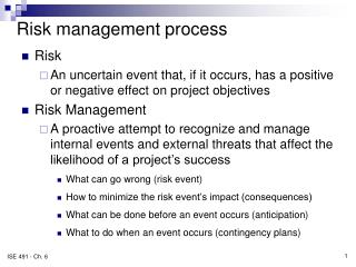
Risk Handling Approach High Moderate Low • Risk a function of: • Likelihood of Failure • Consequences of Failure • Easily diagrammed on a 2-D Chart 5 O 4 - Original O Likelihood 3 X - Current X 2 T - Target T 1 1 2 3 4 5 Consequence Example above is of a risk that has been largely mitigated ARIES San Diego, CA 3-4 March 2008
Risk Likelihoods ARIES San Diego, CA 3-4 March 2008
Risk Consequences Consequences come in three types: Technical, Schedule, and Cost ARIES San Diego, CA 3-4 March 2008
Risk Example Optical Linear Position Sensor Description: The optical position sensor concept has a serial optical position track on the ram shaft. This exposes the optic code and read head to contamination, and the serial track is sensitive to backlash. Risk Source: Technical Likelihood Rationale: The actuator is exposed to water, ice, oily fluids, sand, and dust. Backlash could cause the shaft direction of motion to not match the commanded motion, making a misread of the digital position. Consequence Rationale: The linear sensor could be placed in a sealed case and mechanically connected to the actuator, adding weight and volume. Additional track might solve the backlash problem, but reducing the optical power. Risk Handling Strategy: At the request of the customer, the supplier will be given the opportunity to develop the sensor with the code on the metal shaft. If all mitigation plans for the various risks involved fail, the sensor development contract will be recompeted for a traditional sensor with a code plate in a protected environment. ARIES San Diego, CA 3-4 March 2008
Plan A, Page 1 Description: The optical position sensor concept has a serial optical position track on the ram shaft. This exposes the optic code and read head to contamination, and the serial track is sensitive to backlash. Visibility 5 O X 1412 - Linear Position Sensor Site 4 Program Likelihood Rationale: The actuator is exposed to water, ice, oily fluids, sand, and dust. Backlash could cause the shaft direction of motion to not match the commanded motion, making a misread of the digital position. Likelihood 3 Platform Integration Team 2 Local Consequence Rationale: The linear sensor could be placed in a sealed case and mechanically connected to the actuator, adding weight and volume. Additional track might solve the backlash problem, but reducing the optical power. 1 Phase Archived 1 2 3 4 5 Open Consequence High Evaluation Phase Sensor failed to perform on EMA. Alternative designs using traditional code plates in protected locations have been proposed. Mitigation Plan Status: Type (based on source of risk) - Original O Moderate Technical R X - Current Low Plan: Code-on-Shaft - Baseline Plan A Current Risk Level if Successful Date Action/Event Success Criteria Suc. Comments Schd. ECD Act. L C Initial Plan Risk Level N/A N/A 5 4T 1=Establish sensor power budget. Obtain sample shaft material, form code on shaft, and test code for reflectance and contrast ratio.-CM 7/10/08 7/10/08 Reflectance and contrast ratio with expected readhead performance allow sufficient power to reach detector for clear reading of sensor with TBD accuracy. 4 4T If unsuccessful, fall back to code plate technology already demonstrated on tactical aircraft. Note, if successful, consequence of failure of subsequent step is use of regular code plate in a housing, which has a size and weight impact and so a consequence of 5. ARIES San Diego, CA 3-4 March 2008
Plan A, Page 2 Code-on-Shaft - Baseline Plan A Risk Level if Successful Date Action/Event Success Criteria Suc. Comments Schd. ECD Act. L C 2=Test code for reflectance and contrast ratio in presence of water, ice, oil, and sand and dust with oil.-DP 8/15/08 8/15/08 Measured reflectance and contrast ratio with contamination and with expected readhead performance allow sufficient power to reach detector for clear reading of sensor with TBD accuracy. 4 3T If unsuccessful, fall back to code plate technology already demonstrated on tactical aircraft. Note if successful, consequence of failure of subsequent step is to re-work the optics. Size and weight impact is small, so the consequence of failure becomes 4. 3=Analyze backlash and stiffness of the actuator, compare with sensor bit size and determine if backlash will be a problem.-DP 10/30/08 10/30/08 Either the backlash is less than a sensor bit size, or the actuator stiffness is sufficient to prevent buffeting from moving the shaft through the backlash counter to the commanded motion. 3 3T If unsuccessful, go to mitigation plan B. 4=Develop readhead and test with code for reflectance and contrast ratio.-CM 3/31/09 3/31/09 Reflectance and contrast ratio with contamination and prototype readhead allow sufficient power to reach detector for clear reading of sensor position. 2 3T If unsuccessful, redesign the readhead. Suppose the outcome of Event 3 is not successful ARIES San Diego, CA 3-4 March 2008
Plan B Description: The optical position sensor concept has a serial optical position track on the ram shaft. This exposes the optic code and read head to contamination, and the serial track is sensitive to backlash. Visibility 5 X O Site 4 Program Likelihood Rationale: The actuator is exposed to water, ice, oily fluids, sand, and dust. Backlash could cause the shaft direction of motion to not match the commanded motion, making a misread of the digital position. Likelihood 3 Platform Integration Team 2 Local Consequence Rationale: The linear sensor could be placed in a sealed case and mechanically connected to the actuator, adding weight and volume. Additional track might solve the backlash problem, but reducing the optical power. 1 Phase Archived 1 2 3 4 5 Open Consequence High Evaluation Phase Sensor failed to perform on EMA. Alternative designs using traditional code plates in protected locations have been proposed. Mitigation Plan Status: Type (based on source of risk) O - Original Moderate Technical R X - Current Low Plan: Backlash-countering linear position sensor - Alternate Plan B Current Risk Level if Successful Date Action/Event Success Criteria Suc. Comments Schd. ECD Act. L C Initial Plan Risk Level N/A N/A 3 3T 1=Produce conceptual design for sensor and software that can detect and correct for backlash.-DP 11/10/08 11/10/08 Sensor that detects and corrects for backlash can be designed with existing technologies in existing number of tracks. 3 3T If unsuccessful, develop a design with more tracks, per Alternate Plan C. 2=Develop readhead and test with code for reflectance and contrast ratio.-CM 3/31/09 3/31/09 Reflectance and contrast ratio with contamination and prototype readhead allow sufficient power to reach detector for clear reading of sensor position. 2 3T If unsuccessful, redesign the readhead. Suppose the outcome of Plan B, Event 1 is not successful ARIES San Diego, CA 3-4 March 2008
Plan C Description: The optical position sensor concept has a serial optical position track on the ram shaft. This exposes the optic code and read head to contamination, and the serial track is sensitive to backlash. Visibility 5 X O Site 4 Program Likelihood Rationale: The actuator is exposed to water, ice, oily fluids, sand, and dust. Backlash could cause the shaft direction of motion to not match the commanded motion, making a misread of the digital position. Likelihood 3 Platform Integration Team 2 Local Consequence Rationale: The linear sensor could be placed in a sealed case and mechanically connected to the actuator, adding weight and volume. Additional track might solve the backlash problem, but reducing the optical power. 1 Phase Archived 1 2 3 4 5 Open Consequence High Evaluation Phase Sensor failed to perform on EMA. Alternative designs using traditional code plates in protected locations have been proposed. Mitigation Plan Status: Type (based on source of risk) O - Original Moderate Technical R X - Current Low Plan: Multi-Track Ram Position Sensor Risk - Alternate Plan C Current Risk Level if Successful Date Action/Event Success Criteria Suc. Comments Schd. ECD Act. L C Initial Plan Risk Level N/A N/A 3 3T 1=Design additional sensor track to compensate for backlash.-DP 12/19/08 12/19/08 Analysis indicates additional track will reduce position ambiguity to less than one position track bit width, and that direction ambiguity is not an issue for the system. 3 3T If unsuccessful, redesign backlash compensation track. 2=Review contamination tests and select marking technology.-DP 1/15/09 1/15/09 Reflectance and contrast ratio with lab test readhead allow sufficient light to reach detector for clear reading of sensor position for selected markings. 2 3T If chemical marking is selected, this step is successful, and the risk is reduced to 2, 3, and no seal wear test is needed. If laser marking is selected, the risk stays at 3, 3, and a step to test seal wear is needed. Suppose the outcome of Plan C, Event 1 is also not successful ARIES San Diego, CA 3-4 March 2008
Plan D, Page 1 Description: The optical position sensor concept has a serial optical position track on the ram shaft. This exposes the optic code and read head to contamination, and the serial track is sensitive to backlash. Visibility 5 O X Site 4 Program Likelihood Rationale: The actuator is exposed to water, ice, oily fluids, sand, and dust. Backlash could cause the shaft direction of motion to not match the commanded motion, making a misread of the digital position. Likelihood 3 Platform Integration Team 2 Local T Consequence Rationale: The linear sensor could be placed in a sealed case and mechanically connected to the actuator, adding weight and volume. Additional track might solve the backlash problem, but reducing the optical power. 1 Phase Archived 1 2 3 4 5 Open Consequence High Evaluation Phase Sensor failed to perform on EMA. Alternative designs using traditional code plates in protected locations have been proposed. Mitigation Plan Status: Type (based on source of risk) O - Original Moderate Technical R - Current X Low Plan: High Contrast and Resolution Sensor Track - Alternate Plan D Current Risk Level if Successful Date Action/Event Success Criteria Suc. Comments Schd. ECD Act. L C Initial Plan Risk Level N/A N/A 2 3T 1=Assemble sensor with laser-etched code tracks for laboratory demonstration environments only.-DP 7/31/09 7/31/09 Sensor operates properly at supplier facility and has optical loss and contrast that indicate it will work with a optoelectronic control and cable plant with nominal laboratory environment performance. 2 3T If unsuccessful, rebuild and retest sensor. ARIES San Diego, CA 3-4 March 2008
Plan D, Page 2 High Contrast and Resolution Sensor Track - Alternate Plan D Risk Level if Successful Date Action/Event Success Criteria Suc. Comments Schd. ECD Act. L C 2=Integrate actuator with H-bridge, optoelectronic controller, and cable plant, and demonstrate position sensor operation.-CM 1/31/10 1/31/10 Linear position sensor output matches output from processing shaft angle sensor data in the lab demo environment. 2 3T 1 3T 3/31/10 3/31/10 Closure Event Design validation phase sensor to incorporate different chemical etching technique to form high resolution code tracks and lessons from previous step, and test with read head. Closure Criteria Chemically etched code track achieves same resolution and higher contrast than laser etched track when read by sensor read head Closure Rationale/Verification of Effectiveness: To have reached this step, the sensor must have worked with contaminated surfaces, have met backlash resistance requirements, and operates with chemically etched markings which are smooth and do not affect the seals. ARIES San Diego, CA 3-4 March 2008
Opportunity Management Approach - Original O - Current X High Moderate Low • Opportunity a function of: • Likelihood of the Opportunity Arising • Consequences of taking advantage of the Opportunity • Easily diagrammed on a 2-D Chart T 5 X 4 Likelihood 3 O 2 T - Target 1 1 2 3 4 5 Consequence Example above is of a opportunity that has been largely exploited ARIES San Diego, CA 3-4 March 2008
Opportunity Likelihoods ARIES San Diego, CA 3-4 March 2008
Opportunity Likelihoods ARIES San Diego, CA 3-4 March 2008
Opportunity Consequences Consequences come in four types: Technical, Schedule, Cost, and Producability ARIES San Diego, CA 3-4 March 2008
Opportunity Example Optical Linear Position Sensor Description: Embeddable rad-hard strain sensors would allow monitoring of strain during magnet production, first cool-down, and first field; and, would also allow monitoring of operational strain. Opportunity Source: Technical Likelihood Rationale: Requires development on new types of sensors, such as grating sensors in hollow photonic band gap optical fibers. Consequence Rationale: Would allow major reductions in recurring costs of magnet production, and would allow monitoring of magnet health during use. Opportunity Handling Strategy: Examine capabilities of photoassisted chemical etching of glass, and develop fusion techniques for splicing typical optical fiber to photonic band gap fiber. ARIES San Diego, CA 3-4 March 2008
Plan A, Page 1 Description: Embeddable rad-hard strain sensors would allow monitoring of strain during magnet production, first cool-down, and first field; but, would also allow monitoring of operational strain. Visibility 5 Site T 4 Program Likelihood Rationale: Requires development on new types of sensors, such as grating sensors in hollow photonic band gap optical fibers. Likelihood 3 Platform Integration Team 2 Local Consequence Rationale: Would allow major reductions in recurring costs of magnet production, and would allow monitoring of magnet health during use. 1 X O Phase Archived 1 2 3 4 5 Open Consequence High Achievement Plan Status: Type (based on source of opp) - Original O Moderate Technical G - Current X Low Hollow PBG Optical Fiber Sensors Plan: Baseline Plan A Current Opp Level if Successful Date Action/Event Success Criteria Suc. Comments Schd. ECD Act. L C Initial Plan Opp Level N/A N/A 1 3P 1=Evaluate Translume Inc. and Russian techniques for forming strain-sensitive regions in hollow core PBG fiber.-CM 6/15/08 6/15/08 At least one technique looks viable for maturation within 12 months. 2 3P 2=Supplier develops prototype sensor 6/15/09 6/15/09 Sensor operates in lab environment with TBD sensitivity and accuracy. 3 3P 3=Excitation/Read-Out electronics demonstrates detection of longitudinal and transverse strain.-CM 8/15/09 8/15/09 Both types of strain detected with TBD sensitivity. 3 4P ARIES San Diego, CA 3-4 March 2008
Plan A, Page 2 Embeddable Rad-Hard Magnet Strain Sensors - Plan A Risk Level if Successful Date Action/Event Success Criteria Suc. Comments Schd. ECD Act. L C Closure Event Demonstrate splicing of traditional optical fiber to PBG fiber. Closure Criteria Splicing successful with less than 1 dB loss per splice. 4 4 Closure Rationale/Verification of Effectiveness: 10/15/09 10/15/09 At this point a prototype installable sensor system has been produced with the needed excitation/read-out electronics. ARIES San Diego, CA 3-4 March 2008