Download
1 / 23
230 likes | 247 Views
Learn about Time Division Multiplexing (TDM) and its applications. Explore TDM concepts, advantages, synchronization, examples, and Frame Synchronization. Understand how TDM improves data communication efficiency.

E N D
Chapter 3 • Time Division Multiplexing • The concept of Time Division Multiplexing • TDM Examples • Frame Synchronization • TDM Hierarchy • Packet Transmission Huseyin Bilgekul Eeng360 Communication Systems I Department of Electrical and Electronic Engineering Eastern Mediterranean University
Frequency Division Multiplex • Separation of spectrum into smaller frequency bands • Channel gets band of the spectrum for the whole time • Advantages: • no dynamic coordination needed • works also for analog signals • Disadvantages: • waste of bandwidth if traffic distributed unevenly • inflexible • guard spaces Channels ki k3 k4 k5 k6 c f t
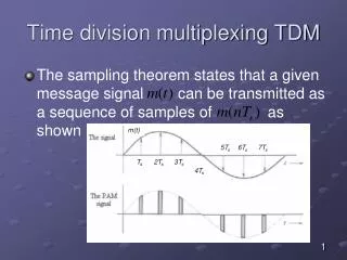
Time Division Multiplex • Channel gets the whole spectrum for a certain amount of time • Advantages: • only one carrier in themedium at any time • throughput high even for many users • Disadvantages: • precise synchronization necessary Channels ki k1 k2 k3 k4 k5 k6 c f t
Time and Frequency Division Multiplex • A channel gets a certain frequency band for a certain amount of time (e.g. GSM) • Advantages: • better protection against tapping • protection against frequency selective interference • higher data rates compared tocode multiplex • Precise coordinationrequired Channels ki k1 k2 k3 k4 k5 k6 c f t
Code Division Multiplex Channels ki k1 k2 k3 k4 k5 k6 • Each channel has unique code • All channels use same spectrum at same time • Advantages: • bandwidth efficient • no coordination and synchronization • good protection against interference • Disadvantages: • lower user data rates • more complex signal regeneration • Implemented using spread spectrum technology c f t
Multiplexing Two basic forms of multiplexing. (a) Frequency-division multiplexing (FDM) (with guardbands).(b) Time-division multiplexing(TDM); no provision is made here for synchronizing pulses. FDM TDM
TDM Composition of one frame of a multiplexed PAM signal incorporating four voice-signals and a synchronizing pulse.
Frequency Division Multiplexing (FDM) Block diagram of FDM system, showing the important constituents of the transmitter and receiver.
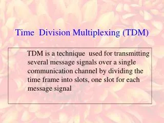
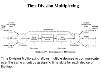
Time Division Multiplexing Definition: Time Division Multiplexing (TDM) is the time interleaving of samples from several sources so that the information from these sources can be transmitted serially over a single communication channel. At the Transmitter • Simultaneous transmission of several signals on a time-sharing basis. • Each signal occupies its own distinct time slot, using all frequencies, for the duration of the transmission. • Slots may be permanently assigned on demand. At the Receiver • Decommutator (sampler) has to be synchronized with the incoming waveform Frame Synchronization • Low pass filter • ISI – poor channel filtering • Feedthrough of one channel's signal into another channel -- Crosstalk Applications of TDM: Digital Telephony, Data communications, Satellite Access, Cellular radio.
Time Division Multiplexing Conceptual diagram of multiplexing-demultiplexing. PAM TDM System
Digital Time Division Multiplexing • Time Division Multiplexing (TDM) can be accomplished at bit or byte (word) level. • Channhels having different data rates can also be TDM multiplexed but must be interleaved accordingly. Digit Interleaving Interleaving channel with different bit rates WORD or Byte Interleaving Interleaving channel with different bit rates using two multiplexers
Block diagram of TDM system. PAM TDM System A Typical Framing Structure for TDM
Time Division Multiplexing Frame structure of a certain TDM signal Composite Signal Format
Time Division Multiplexing Pulse width of TDM PAM: Pulse width of TDM PCM:
Pulse Stuffing in TDM • Stuff bits, which are dummy bits are inserted in the TDM output data when the different inputs are not completeley synchronized or the different input rates are not related by a ratinal number.
Pulse Stuffing in TDM • Stuff bits, which are dummy bits are inserted in the TDM output data when the different inputs are not completeley synchronized or the different input rates are not related by a ratinal number. Multiplexing of two data streams with bit stuffing
TDM Example (Multiplexing Analog and Digital) • Source 1: 2 kHz bandwidth. • Source 2: 4 kHz bandwidth. • Source 3: 2 kHz bandwidth. • Source 4-11: Digital 7200 bits/sec. 16 ksam/s 64 kb/s 8x7.2=57.6 kb/sUse stuff bits to complete 7.2 to 8 kb/s.Now 8 and 64 rates are complete multıples 128 kb/s
Frame Synchronization • To sort and direct the received multiplexed data to the appropriate output channel • Two ways to provide frame sync to the demultiplexer circuit - Over a separate channel - Deriving from the TDM signal itself • Frame sync (unique k-bits) +Information words of an N-channel TDM system
Packet Transmission System • TDM is Synchronous Transfer Mode (STM) technology - Data source is assigned a specific time slot – fixed data rate - More efficient when sources have a fixed data rate - Inefficient to accommodate bursty data source Solution? • Packet Transmission System - Partitions source data into data packets (destination address, header) - Efficiently assigns network resources when the sources have bursty data - Examples : Internet TCP/IP technology and the Asynchronous Transfer Mode (ATM) technology.
Summary • How information in analog waveforms can be represented by digital signaling • How to compute the spectra for line codes • How filtering of the digital signal, due to the communication channel affects our ability to recover the digital information at the receiver [ISI] • How we can merge information from several sources into one digital signal by using time division multiplexing (TDM)