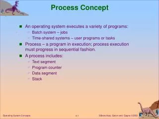
Process concept
Multiprogramming enhances CPU utilization by allowing multiple programs to reside in memory simultaneously. This concept addresses the inefficiency caused by a single program running while waiting for I/O operations, leaving the CPU idle. Multiprogramming interleaves the execution of two or more programs, enabling better resource sharing. A process, defined as a program in execution, transitions through various states, controlled by a Process Control Block (PCB). The management of processes, including their creation, states, and resource allocation, is vital to optimizing system performance.

Process concept
E N D
Presentation Transcript
Concept of Multiprogramming • When there is a single program running in the CPU, it leads to the degradation of the CPU utilization. • Example: When a running program initiates an I/O operation, the CPU remain idle until the I/O operation is completed. Solution to this problem is provided by Multiprogramming.
Multiprogramming Continued.. Definition: A mode of operation that provides for the interleaved execution of two or more programs by a single processor.
Multiprogramming Continued.. Improving CPU utilization By allowing several programs to reside in main memory at the “same time” the CPU might be shared, such that when one program initiates an I/O operation, another program can be assigned to the CPU, thus the improvement of the CPU utilization.
Multiprogramming Continued.. Implementation The concept of process need to be introduced in order to understand multiprogramming and the concurrent execution of sequential processes in a computer system. What is a process?
Process • Definition: • A program in execution • An asynchronous activity • The “locus of control” of a procedure in execution • It is manifested by the existence of a process control block (PCB) in the operating system.
Process States A state of a process describes the activity that the process is doing at a certain moment in time. New : A newly created process, not in the ready queue. Ready : It can use the CPU , if available. Running : If it is currently in the CPU. Waiting : Waiting for some event ex: I/O Abend : Stops executing due to an error. End : Finished executing properly. Suspended: Stops temporarily while the OS uses the CPU
States of processes SUSPENDED END NEW RUNNING READY WAITING I/O ABEND
Causes of state change When a process executes, it changes states and interrupts cause process to change states. Current StateNew state Interrupt Running End EOP ( End of Program) Running ABEND Trap (Abnormal end) Running Blocked System Call (Start I/O) for I/O (SIO)
Depiction of state change EOP END TRAP RUNNING ABEND SIO BLOCKED
Process Continued… • The activity of a process is controlled by a data structure called Process Control Block(PCB). • A PCB is created every time a program is loaded to be executed. • So, a process is defined by PCB-Program couple.
Structure of PCB • PCB contains information about processes, for instance: • the current state of a process • Unique identification of process • Process priority • Contents of some CPU registers • Instruction Pointer (IP), also known as PC • Base and limit registers • Time limits and I/O status information
Structure of PCB Contd… ….. Pointer to next PCB Process name or ID Base code PROGRAM Limit Code …. IP or PC Stack Pointer Thread Control Block (TCB) STACK Registers State MODE Interrupt Flags .….
Process Continued… A thread is known as “the unit of execution” of a process and it is represented by the Thread Control Block (TCB). The TCB consists of four fields: PC, stack pointer, the contents of some registers, and the state.
Process Continued… We can now observe how each stage of a process takes place by the aid of a state diagrams. Process creation : • An OS can create one or more processes, via a create-process system call. • During the course of execution an user process may create new processes or threads as well. In this case, the creating process (thread) is called the parent and the created (new) process (thread) is named the child.
Process Creation New Create Ready The process is created and then inserted at the back of the ready queue, it moves to the head of the queue according to a scheduling policy.
Process Creation Contd… Program Load PCB OS code stack Create
Process Creation (closer view) Cont… Create OS stack Load PCB Program file heap header bss data data code code symbol table Process working space Disk Memory
Process working space (run-time environment) stack Dynamic link, return address, Local variables, function Parameters, … malloc(n); heap Dynamically allocated variables int z; bss Global and static variables int y = 7; data Constants / initialized data x = 4; Program text (write protected) code Process working space
Process working space (run-time environment) Process working space sum Local Local bss: means “block started by symbol” and has that name for historical reasons. void sub(float total, int part ) { int List[5]; float sum; … } Local Local stack Local Local Parameter Activation record Parameter malloc(n); heap int z; bss Dynamic Link int y = 7; data Return Address x = 4; code
Thread working space (run-time environment) Multithreading: Each thread is a unit of execution. stack-T1 Multithreaded processes need a stack per thread. All threads shared the same address space. Each thread has is own TCB. stack-T2 stack-main heap bss data code
Thread working space (run-time environment) Multithreading: All threads share the CPU-PC and CPU-SP. In this picture thread-T1 is using the CPU. PCB stack-T1 Process ID TCB-T1 SP PC regs state TCB-T2 stack-T2 regs state SP PC TCB-main CPU regs state SP PC stack-main sp . . . pc heap regs Open files bss Other resources data . . . code
Memory snap shot of two processes in Ready State INTERRUPT HANDLER RUNTIME LIBRARY LOADER DISPATCHER RUNNING READY NULL PCB1 PCB2 stack stack 1 2 The PCB is stored in the OS memory area in a linked list.
Ready to Running Dispatcher RUNNING READY Timer Interrupt When a process reaches the head of the queue and the CPU is available, the process is dispatched which means that the CPU is assigned to the process. This cause a transition from the ready state to the running state. When the time slice of the running process expires it goes back to the ready state.
Ready to Running INTERRUPT HANDLER RUNTIME LIBRARY LOADER DISPATCHER RUNNING READY PCB1 PCB2 stack stack 1 2 INTERRUPT FLAGS MASK IP Mode OV MP PI TI I/O SVC TO BE DEFINED LATER CPU Accumulator
Ready to Running INTERRUPT HANDLER RUNTIME LIBRARY LOADER DISPATCHER RUNNING READY PCB1 PCB2 PCB2 stack stack stack 1 2 2 INTERRUPT FLAGS MASK IP OV MP PI TI I/O SVC TO BE DEFINED LATER Mode CPU Accumulator
Running to Ready INTERRUPT HANDLER RUNTIME LIBRARY LOADER DISPATCHER RUNNING READY PCB2 PCB1 stack stack 1 2 INTERRUPT FLAGS MASK IP Mode CPU OV MP PI TI I/O SVC TO BE DEFINED LATER Accumulator
Running to Ready INTERRUPT HANDLER RUNTIME LIBRARY LOADER DISPATCHER RUNNING READY PCB2 PCB2 PCB1 PCB1 stack stack stack stack 1 2 2 1 INTERRUPT FLAGS MASK IP Mode CPU OV MP PI TI I/O SVC TO BE DEFINED LATER Accumulator
Process Continued… As the OS switches the allocation of CPU among processes it uses the PCB to store the CPU information or context, which represents the state of the process. In the previous example we have seen how the OS performed a context switch between processes P2(from Running to Ready) and P1(from Ready to Running). When a context switch occurs we need to save the state of the running process in its PCB and load the state of the new process in the CPU.
Case of Timer interrupt Dispatch P2 P1 RUNNING READY Timer Interrupt After a timer interrupt, the OS move P1 back to the ready state and the CPU Is assigned to P2.
Context switching P1 OS P2 EXECUTING WAITING TIMER Save state into PCB1 WAITING WAITING Reload state from PCB2 DISPATCH WAITING EXECUTING TIMER Save state into PCB2 WAITING WAITING Reload state from PCB1 DISPATCH EXECUTING WAITING
Case of I/O interrupt RUNNING READY Start I/O (System call) WAITING I/O Interrupt
Case of I/O interrupt Contd.. INTERRUPT HANDLER RUNTIME LIBRARY LOADER DISPATCHER RUNNING READY PCB2 PCB3 PCB1 SIO I/O INTERRUPT FLAGS MASK I/O DEVICE IP OV MP PI TI I/O SVC TO BE DEFINED LATER Accumulator
Case of I/O interrupt Contd.. INTERRUPT HANDLER RUNTIME LIBRARY LOADER DISPATCHER RUNNING READY PCB2 PCB1 PCB2 PCB3 PCB3 I/O INTERRUPT FLAGS MASK I/O DEVICE IP OV MP PI TI I/O SVC TO BE DEFINED LATER Accumulator
Case of I/O interrupt Contd.. INTERRUPT HANDLER RUNTIME LIBRARY LOADER DISPATCHER RUNNING READY OS PCB1 PCB2 PCB3 I/O SUSPEND INTERRUPT FLAGS MASK I/O DEVICE IP OV MP PI TI I/O SVC TO BE DEFINED LATER Accumulator
Case of I/O interrupt Contd.. INTERRUPT HANDLER RUNTIME LIBRARY LOADER DISPATCHER RUNNING READY OS PCB1 PCB3 PCB2 PCB3 I/O SUSPEND INTERRUPT FLAGS MASK I/O DEVICE IP OV MP PI TI I/O SVC TO BE DEFINED LATER Accumulator
Context switching P3 OS P2 EXECUTING READY SIO Save state into PCB3 Put P3 into the I/O queue READY WAITING IN I/O QUEUE EXECUTING Reload state from PCB2 DISPATCH IN I/O STATE WAITING EXECUTING I/O INTERRUPT Suspend P2 HANDLE I/O READY STATE SUSPENDED Put P3 in Ready state Resume P2 DISPATCH READY STATE EXECUTING WAITING
Handling I/O: Here the process waiting in the I/O queue is moved back to the ready state after the I/O request is completed.
End of Process END EOP RUNNING TRAP ABEND
ABORT PROGRAM • ERROR MESSAGE • FREE RESOURCES • DELETE PCB PCB TRAP prog stack OS EOP • PROGRAM RUNS SUCCESSFULLY • FREE RESOURCES • DELETE PCB