Chapter 5 Data Encoding
Chapter 5 Data Encoding. Review. Information: Numeric Data, characters, voice, pictures, codes or any massage that can be read by and has meaning to human and machine. Review. For transmission: Information must be converted into binary first. ASCII table Unicode

Chapter 5 Data Encoding
E N D
Presentation Transcript
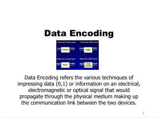
Review Information: Numeric Data, characters, voice, pictures, codes or any massage that can be read by and has meaning to human and machine.
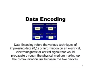
Review • For transmission: • Information must be converted into binary first. • ASCII table • Unicode • Information must be encoded into electromagnetic signals. (Analog or digital)
Review • Digital Signal: • A digital signal is a sequence of discrete discontinuous voltage pulses. • Each pulse is a signal element • In its simplest form each signal element represents a binary 0 or 1.
Data Encoding Both analog and digital information can be encoded as either analog or digital. (Function of media and communication ) • Digital data, digital signal • Digital data, analog signal • Analog data, digital signal • Analog data, analog signal
Terminology (digital signal) • Unipolar encoding: If the signal elements all have the same algebraic signs, all positive or all negative, the signal is called unipolar. • Polar encoding: One logical state is represented by positive voltage and the other by the negative voltage level.
Terminology (digital signal) • Data rate: The rate in bits per second that the data is transmitted. (R) • Bit duration: The amount of time for one bit transmission (1/R) • Modulation rate: The rate at which the signal level is changed. (baud rate, signal levels per second)
Terminology • Encoding scheme: The mapping from data bits to signal elements • Spectrum: The spectrum of a signal is the range of frequencies that it contains. • Absolute bandwidth: The width of the spectrum • Effective bandwidth: The are of the bandwidth where most of the energy of the signal is concentrated.
Terminology • DC (direct current)component: A component of a signal with the frequency of zero. • Example • S(t)=1+(4/)sin(2 ft) + ….
Evaluation of Various Encoding Techniques (affecting factors) • Signal spectrum: • Lack of high frequency components means less bandwidth required for transmission • DC component: It is desirable to have no DC component. (easier implementation) • Clocking: The beginning and end of each bit position must be determined. • Providing separate clocking information. • Implementation of some other ways of synchronization
Evaluation of Various Encoding Techniques (affecting factors) • Error detection: • To detect errors more quickly, some error detection techniques must be built into signaling encoding methods. • Signal interference and noise immunity: • Some signal encoding techniques provide better error rate (BER) than others • Cost and complexity
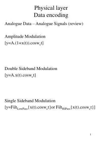
Data Encoding Digital data, analog signal • A modem converts digital data to analog data • Amplitude –shift keying (ASK) • Frequency –shift keying (FSK) • Phase –shift keying (PSK)
Data Encoding Analog data, Digital signals • Pulse code modulation (PCM) • Samples analog data periodically • Quantizing (limiting the possible values to discrete set of values) the samples
Data Encoding Digital data, digital signal • Simplest form of digital encoding • Two voltage level required • It can be enhanced to improve performance.
Digital–to-Digital Encoding Schemes • Unipolar • Uses only one level of voltage (almost obsolete) • Polar • Uses two level of voltage • Bipolar • Uses theree level of voltage
Unipolar Encoding • Presence and absence of a voltage level is used for two binary digits. • The absence of voltage could represent zero. • A constant positive voltage could represent 1.
Unipolar Amplitude 0 1 0 0 0 Time
Unipolar Encoding Issues • Synchronization: A major issue: • Example: For a bit rate of 1000 bps, the receiving device must measure each bit for 0.005 s. • DC Component: • The average amplitude of a unipolar encoded signal is not zero. • This creates a DC component ( a component with zero frequency). • DC component can not travel through some media that can not handle DC component
Polar Encoding Polar encoding uses tow voltage levels (positive and negative)
Polar NRZ RZ Biphase Differential Manchester NRZ-L NRZ-I Manchester
Variation of Nonreturn to Zero (NRZ) NRZ-L, Nonreturn to Zero-level (polar) • The level of the signal depends on the type of the bit it represents (a positive voltage usually represents bit 0 and negative voltage represents the bit 1 (or vice versa) • The problem exist when receiver needs to interpret long streams of 1 or zero. Or NRZ-I (Nonreturn to Zero Invert on ones)
Nonreturn to Zero-Level Amplitude 1 1 1 0 1 0 0 0 Time
Variation of Nonreturn to Zero (NRZ) NRZ-I (Nonreturn to Zero Invert on ones) • An inversion of voltage level represents a 1 bit. • The transition between a positive and negative voltage represents a 1 not the voltage level itself. • A 0 is represented by no change • Still a string of zeros is a problem.
Nonreturn to Zero, invert on ones Amplitude 1 1 0 1 0 1 0 0 0 Time
Nonreturn to Zero-Level Nonreturn to Zero, invert on ones Amplitude 0 1 0 0 1 1 1 0 Time 0 1 0 0 0 1 1 1 0
Return to Zero • One solution to synchronization issue of NRZ-L and NRZ-I is using RZ (Return to Zero) encoding schemes. • It uses three values: positive, negative and zero. • In RZ, the signal changes during each bit. • A 1 bit is represented by positive-to zero and a 0 bit by negative-to-zero.
Return to Zero It requires two signal changes to encode one bit. (uses more bandwidth) 0 1 0 0 1 1 1 Time These transitions can be used for synchronization
NRZ pros and cons • Pros • Easy to engineer • Make good use of bandwidth • Cons • dc component • Lack of synchronization capability • Used for magnetic recording • Not often used for signal transmission
Polar NRZ RZ Biphase Differential Manchester NRZ-L NRZ-I Manchester
Biphase Encoding • The most popular encoding to deal with the synchronization problem. • The signal changes at the middle of the bit interval and continues to the opposite pole (dose not return to zero). • Types of biphase encoding: • Manchester • Differential Manchester
Biphase Encoding • Manchester Encoding: • The inversion at the middle of each bit is used for both synchronization and bit representation • i.e. Transition serves as clock and data • Low to high represents one • High to low represents zero • Used by IEEE 802.3
Differential Encoding • Data represented by changes rather than levels • More reliable detection of transition rather than level • In complex transmission layouts it is easy to lose sense of polarity
Biphase Encoding • Differential Manchester: • Transition at the middle of bit interval is used for clocking only. • Transition at the start of a bit period represents zero. • No transition at start of a bit period represents one. • Note: this is a differential encoding scheme • Used by IEEE 802.5.
Differential Manchester Encoding Presence of transition at the beginning of the bit interval represents zero. Absence of transition at the beginning of the bit interval represents one.
Biphase Pros and Cons • Con • At least one transition per bit time and possibly two • Maximum modulation rate is twice NRZ • Requires more bandwidth • Pros • Synchronization on mid bit transition (self clocking) • No dc component • Error detection • Absence of expected transition
Multilevel Binary Use more than two levels • Bipolar-AMI (Alternate mark inversion) • Pseudoternary (variation of Bipolar-AMI)
Bipolar Encoding • Uses there voltage levels • Positive, negative, and zero • Zero level represents binary 0 • One’s are represented by alternating positive and negative voltages
Types of Bipolar Encoding • Bipolar Alternate Mark Inversion (AMI) • Bipolar 8-zero substitution (B8ZS) • High density bipolar 3 (HDB3)
Bipolar Alternate Mark Inversion (AMI) • Mark comes from telegraphy (meaning 1) • Zero voltage represents zero • Binary 1’s are represented by alternating positive and negative voltages
Bipolar Alternate mark inversion (AMI)
Types of Bipolar Encoding • Pros: • DC component is zero • A long sequence of 1’s is always synchronized. • Lower bandwidth • Easy error detection • Cons • No mechanism for synchronization of long string of zeros
Variation of AMI • Bipolar 8-zero substitution (B8ZS) • (implemented in US) • High Density bipolar 3 (HDB3) • (implemented in Europe) • In both methods the original pattern is modified in the case of multiple consecutive zeros.
Bipolar 8-zero substitution (B8ZS) • It works similar to BMI • Whenever 8 or more consecutive zeros occurs, signal level is forced to change.
Pseudoternary • One represented by absence of line signal • Zero represented by alternating positive and negative • No advantage or disadvantage over bipolar-AMI
Trade Off for Multilevel Binary • Not as efficient as NRZ • Each signal element only represents one bit • In a 3 level system could represent log23 = 1.58 bits • Receiver must distinguish between three levels (+A, -A, 0) • Requires approx. 3dB more signal power for same probability of bit error
Scrambling • Use scrambling to replace sequences that would produce constant voltage • Filling sequence • Must produce enough transitions to sync • Must be recognized by receiver and replace with original • Same length as original • No dc component • No long sequences of zero level line signal • No reduction in data rate • Error detection capability
B8ZS • Bipolar With 8 Zeros Substitution • Based on bipolar-AMI • If octet of all zeros and last voltage pulse preceding was positive encode as 000+-0-+ • If octet of all zeros and last voltage pulse preceding was negative encode as 000-+0+- • Causes two violations of AMI code • Unlikely to occur as a result of noise • Receiver detects and interprets as octet of all zeros