Download
1 / 35
350 likes | 381 Views
Step-by-step guide on creating a detailed airplane wing, engine cowling, and cockpit in a 3D modeling software. Learn lofting, shelling, and extrusion techniques.

E N D
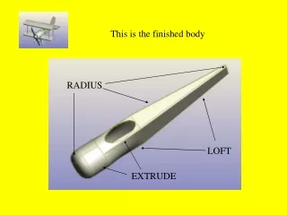
This is the finished body RADIUS LOFT EXTRUDE
Creating the body taper • Open the wing • Click on new part in context
Rotate the wing using the keyboard arrows • View the wing from the side
Make sure the workplane selector is presses • Select the frontal workplane by clicking on it when it goes bright blue
Select the workplane menu • Select new workplane • Make sure offset is selected • Call it plane middle • Drag it to the side using the yellow handle
Select the frontal workplane by clicking on it (Make sure workplane selector is selected) • Select new workplane from the workplane menu • Make sure offset is selected and call it plane rear • Drag the workplane to the other side using the yellow handle
Make sure the workplane selector is selected • Click on the rear workplane to select it • Go to the workplane menu and click on new sketch • Call it plane rear • Make sure filled is ticked • Make sure plane rear is selected
Select the rectangle drawing tool • Click on the design and hold the left hand button down • Drag the mouse down so a rectangle like this is drawn. • Select all the sides by clicking on the shape selector and dragging a box round them ( they will go red) • Click and hold on it to drag it so it is central
Click on the workplane selector • Click on the frontal workplane • Select the workplane menu and click on new sketch • Call the sketch plane middle and make sure fill is clicked. Make sure it is on the frontal workplane
Rotate the design using the keyboard arrows to look straight onto the workplane • Use the rectangle tool to draw a rectangle. • Click once on a side to select it then click and hold to drag the side so the rectangle is central on the rear rectangle. Adjust each side like this
Turn the drawing using the keyboard arrows so you can see both sketches
Click on the shape selector • Click at the top of the design and hold the left mouse button then drag a box round both sketches to select them as one
From the assembly menu select loft • Make sure the sketches appear in the profile menu
Change the lofting path by clicking and dragging on the yellow handle so it goes from one corner to the other in a straight line
Click on the workplane selector • Select the plane middle workplane with one click • Look straight on to it by rotating the design • Go to the workplane menu and create a new stetch . • Make sure it is filled and on the plane middle workplane • Use the circle tool to add a circle to the drawing, make it central to the rectangle. • Click on the shape selector then on the circle to drag it Creating the front engine cowling
Turn the drawing using the keyboard arrows • Select both sketches by clicking on the shape tool and dragging a selection box round both • Select loft from the features box and align the corners if needed using the yellow handle. • Make sure round and plane middle are in the profile box and add material is selected
Select the edges of the shape in pairs. Do this by clicking on the edge selector • Click on the first edge to select it • Press shift and hold it down • Click on the other, both lines should now be selected (red) • Click on the radius tool • Use the yellow handles to apply the radius • Click on o.k. when this is correct
Once you have done all the sides turn the drawing round using the keyboard arrows and select the face selector • Click on the end face of the body
Add a radius to the end face • Select the round edge tool • Type in a radius that matches the radius applied to the sides • Click on o.k.
Shelling an object • Rotate the body using the keyboard arrows • Select the surface selector and click on the end face • Select shell solid at a thickness of 1mm. • Click o.k.
Select the plane middle workplane by clicking on the workplane selector then clicking on the workplane • Go to the workplane menu and select new workplane • Check filled is ticked and plane middle workplane is selected • Click on the circle tool • draw a circle of the same diameter as the existing circle • Select both using the shape selector and the shift key • Click on the concentric circle key to give them the same centre.
Click on the dimension tool • Click on the new circle • Click on the dimension twice quickly and the properties box should appear • Change the length so it matches the first circle
Click on extrude • Check add material is selected • Drag the extrusion using the handle
Select the edge using the edge selector. • Click on the round edge tool • Use the handle to drag the radius
The body should look like this. • Click on the workplane selector to show all the workplanes. • Select the base workplane by clicking on it once.
Creating the cock pit • Select the workplane menu • Click on new workplane • Use the handle to drag the new workplane above the body, click hold and drag • Change the name to cut out
Select the cutout workplane, do this by; • Clicking on the workplane selector then click on the cut out workplane • Look directly down onto it using the keyboard arrows
Click on the workplane menu • Click on new sketch • Call the sketch hole, check filled is clicked and the workplane is cut out
Draw an oval above the main body using the oval tool. • Select it by clicking once and adjust the sides by clicking again and holding then dragging • Do this in the middle and at the end
Extrude the oval. • Rotate the drawing using the keyboard arrows • Click on the extrude tool • Make sure subtract material is selected. • Drag the shape downward using the handle
Go to the window menu • Select split to see the body in all directions Save to the plane file