2G & 3G — CDMA Code Division Multiple Access
Frequency. 2G & 3G — CDMA Code Division Multiple Access. Code. Spread spectrum modulation Originally developed for the military Resists jamming and many kinds of interference Coded modulation hidden from those w/o the code All users share same (large) block of spectrum

2G & 3G — CDMA Code Division Multiple Access
E N D
Presentation Transcript
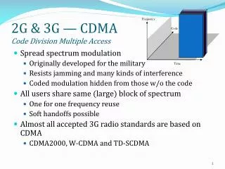
Frequency 2G & 3G — CDMACode Division Multiple Access Code • Spread spectrum modulation • Originally developed for the military • Resists jamming and many kinds of interference • Coded modulation hidden from those w/o the code • All users share same (large) block of spectrum • One for one frequency reuse • Soft handoffs possible • Almost all accepted 3G radio standards are based on CDMA • CDMA2000, W-CDMA and TD-SCDMA Time
Spread Spectrum • Spread spectrum is a communication technique that spreads a narrowband communication signal over a wide range of frequencies for transmission then de-spreads it into the original data bandwidth at the receive. • Makes jamming and interception harder • Two Techniques: • Frequency hoping • Signal broadcast over seemingly random series of frequencies • Direct Sequence • Each bit is represented by multiple bits in transmitted signal • Chipping (spreading)code/sequence
Spread Spectrum Concept • Input fed into channel encoder • Produces narrow bandwidth signal around central frequency • Signal modulated using sequence of digits • Spreading code/sequence • Typically generated by pseudonoise/pseudorandom number generator (PN) • Increases bandwidth significantly • Spreads spectrum • Receiver uses same sequence to demodulate signal • Demodulated signal fed into channel decoder
Spread spectrum Concept
Frequency Hopping Spread Spectrum (FHSS) • Signal broadcast over seemingly random series of frequencies • Receiver hops between frequencies in sync with transmitter • Eavesdroppers hear unintelligible blips • Jamming on one frequency affects only a few bits HedyLamarr
Basic Operation • Typically 2k carriers frequencies forming 2k channels • Channel spacing corresponds with bandwidth of input • Each channel used for fixed interval • 300 ms in IEEE 802.11 • Some number of bits transmitted using some encoding scheme • May be fractions of bit (see later) • Sequence dictated by spreading code
f4 f3 f2 f1 Time Frequency FHSS Repeating period Spreading Factor
f4 f3 f2 f1 Time Frequency FHSS Repeating period
f4 f3 f2 f1 Time Frequency Multiplexing Repeating period User1 User2
f4 f3 f2 f1 Time Frequency Multiplexing Repeating period User1 User2
Slow and Fast FHSS • Frequency shifted every Tc seconds • Duration of signal symbol is Ts seconds • Slow FHSS has Tc Ts • Fast FHSS has Tc < Ts • Generally fast FHSS gives improved performance in noise (or jamming)
Direct Sequence Spread Spectrum (DSSS) • Each bit represented by multiple bits using spreading (chipping)code/sequence. This process is called Processing Gain. • The bits resulting from combining the information bits with the chipping code are called chips - the result- which is then transmitted. • Spreading code spreads signal across wider frequency band • In proportion to number of bits used • 10 bit spreading code spreads signal across 10 times bandwidth of 1 bit code Processing Gain Spreading Factor (SF)dB =10 log10(10)=10 dB • SF is the number of chips within each symbol duration , let be the chip duration : chipping rate, : Baud rate. • One method: • Combine input with spreading code using XOR • Input bit 1 inverts spreading code bit • Input zero bit doesn’t alter spreading code bit • Data rate equal to original spreading code • Performance similar to FHSS
Approximate Spectrum of DSSS Signal BW: The BW of is
Direct Sequence Spread Spectrum Transmitter Modulator Multiplier
Direct Sequence Spread Spectrum Receiver Spread Signal Original Signal
DSSS Overall Transmit/Receive transmit signal spread spectrum signal user data RF Modulator X chipping sequence radio carrier : we can look at it as a pulse shaping PN generator transmitter correlator lowpass filtered signal sampled sums products received signal data RF Demodulator integrator decision X chipping sequence receiver radio carrier Because of Noise PN generator
DSSS Using BPSK • Multiply BPSK signal, by [takes values +1, -1] to get • amplitude of signal • carrier frequency • digital baseband signal • pulse shaping signal • bit duration • At receiver, incoming signal multiplied by • Since, , original signal is recovered
Narrowband vs. Spread Spectrum Narrowband (High Peak Power) Power Spread Spectrum (Low Peak Power) Frequency The bandwidth increases with spreading but spectral power density necessary for transmission decreases. Spread spectrum needs only very small power densities, often below the level of natural background noise.
Gains • Immunity from various noise and multipath distortion • Including jamming • Can hide/encrypt signals • Only receiver who knows spreading code can retrieve signal • Advantages • reduces frequency selective fading • in cellular networks • base stations can use the same frequency range • several base stations can detect and recover the signal • soft handover • Disadvantages • precise power control necessary
signal Interference or noise power spread signal power spread Interference or noise detection at receiver f f Gains (cont.) • Problem of radio transmission: frequency dependent fading can wipe out narrow band signals for duration of the interference • Solution: spread the narrow band signal into a broad band signal using a special code - protection against narrow band interference spread spectrum channels channelquality channelquality narrowband channels 2 2 2 2 1 5 6 2 2 3 1 4 frequency frequency Narrowband signal spreadspectrum guard space
Effects of spreading on noise and interference Rx x + The noise is spread
Effects of spreading and interference PSD PSD user signal broadband interference narrowband interference i) ii) f f sender PSD PSD PSD iii) iv) v) f f f receiver
Code Division Multiple Access (CDMA) • Multiplexing Technique used with spread spectrum • Start with data signal rate • Buad rate (symbols per second) • Break each symbol into SF chips according to fixed pattern specific to each user (User’s spreading code) • SF is the number of chips within each symbol duration , let be the chip duration • New channel has chip data rate chips per second (cps). • Spreading code repetition period (code length) : • Short code: an exact pattern of the PN will repeat each data symbol. • Long code:
Short vs. Long Code Short 1 0 1 1 0 1 0 0 1 0 0 1 0 1 1 0 1 0 0 1 0 1 0 0 1 0 1 0 1 1 0 0 1 0 1 1 0 1 1 0 Long 1 0 0 1 1 0 0 1 1 0 0 1 0 1 0 0 0 1 0 1 1 1 0 0 1 0 0 1 0 0 1 1
CDMA Example • e.g. SF=6, three users (A,B,C) communicating with base receiver R • Code for A = <1,-1,-1,1,-1,1> • Code for B = <1,1,-1,-1,1,1> • Code for C = <1,1,-1,1,1,-1> Short code
CDMA Explanation • Consider A communicating with base • Base knows A’s code • Assume communication already synchronized • A wants to send a 1 • Send chip pattern <c1, c2, c3, c4, c5, c6>, e.g.<1,-1,-1,1,-1,1> • A’s code • A wants to send 0 • Send chip pattern <-c1, -c2, -c3, -c4, -c5, -c6>, e.g.<-1,1,1,-1,1,-1> • Complement of A’s code • Receiver knows sender’s code and performs electronic decode function • <d1, d2, d3, d4, d5, d6> = received chip pattern • <c1, c2, c3, c4, c5, c6> = sender’s code • Decoder ignores other sources when using A’s code to decode • Orthogonal codes
CDMA Example • User A code = <1, –1, –1, 1, –1, 1> • To send a 1 bit = <1, –1, –1, 1, –1, 1> • To send a 0 bit = <–1, 1, 1, –1, 1, –1> • User B code = <1, 1, –1, – 1, 1, 1> • To send a 1 bit = <1, 1, –1, –1, 1, 1> • To send a 0 bit = <–1,–1, 1, 1,–1,–1> • Receiver receiving with A’s code • (A’s code) x (received chip pattern) • User A ‘1’ bit: 6 1 • User A ‘0’ bit: -6 0 • User B ‘1’ bit: <1, –1, –1, 1, –1, 1>X<1, 1, –1, –1, 1, 1>=0 unwanted signal ignored
CDMA for DSSS • n users each using different orthogonal PN sequence • Modulate each users data stream • e.g. Using BPSK • Multiply by spreading code of user
correlator lowpass filtered signal sampled sums products received signal data demodulator integrator decision X chipping sequence receiver radio carrier PN generator
Multiple Access Interference (MAI) X integrator X integrator X X . . . . . . X integrator X Channel • Compute the interference at the output of one receiver caused by the remaining M-1 users. • Focus on the time interval and the kth symbol of all users. • The th user transmit one symbol over the time interval . • Each user receives the kth symbol of all users within . • The ith user’s transmitted power is . • The ith user’s channel has a gain .
MAI Where Is the time-varying cross-correlation between two spreading codes. • For short code are periodic and the period is , the spreading codes are identical over each interval the cross correlation between two spreading codes is a constant with respect to k (does not change with k)
MAI • Where is the MAI • Where the spreading codes are selected to be orthogonal i.e. So
Pseudorandom Numbers • Also called Pseudonoise(PN) because the autocorrelation of it resembles that of a white noise (an impulse). • Generated by algorithm using initial seed • Deterministic algorithm • Not actually random • If algorithm good, results pass reasonable tests of randomness • Need to know algorithm and seed to predict sequence • Pseudonoise(PN) sequence chosen so that its autocorrelation is very narrow PSD is very wide, in order to make the correlation between a code and a shifted version of it approximately zero. • Concentrated around t <Tcto • Cross-correlation between two codes is very small, if it is zero Orthogonal.
Tc t LTc -1/L -LTc PN Sequence Generation • Codes are periodic and generated by a shift register and XOR • Maximum-length (ML) shift register sequences (m-sequence), m-stage shift register, length: bits 1 -Tc D D D D … D D Delay tap by (shift register) XOR (Modulo-2 adder) Output
Generating PN Sequences Finite State Machine (FSM) • Take m=2 L=3 • cn=[1,1,0,1,1,0, . . .], usually written as bipolar cn=[1,1,-1,1,1,-1, . . .] Output 00 01 + Dead state 0 1 11 10 1
Properties of m-sequences • The cross correlation between an m-sequence and noise is low • This property is useful to the receiver in filtering out noise • The cross correlation between two different m-sequences is low • This property is useful for CDMA applications • Enables a receiver to discriminate among spread spectrum signals generated by different m-sequences • Easy to guess connection setup in 2m samples so not too secure • In practice, Gold codes or Kasami sequences which combine the output of m-sequences are used.
Gold Codes • Gold sequences constructed by the XOR of two m-sequences with the same clocking • Codes have well-defined cross correlation properties • Only simple circuitry needed to generate large number of unique codes